Base station, radio terminal and radio communication method

a radio terminal and radio communication technology, applied in the field of base station, radio terminal and radio communication method, can solve the problems of reducing the speed of communication from the terminal to the base station, other terminals cannot easily know,

Inactive Publication Date: 2007-10-04
KK TOSHIBA
View PDF0 Cites 46 Cited by
  • Summary
  • Abstract
  • Description
  • Claims
  • Application Information

AI Technical Summary

Benefits of technology

[0028]measuring communication quality of the unassigned frequency channels; and
[0029]transmitting information indi

Problems solved by technology

However, according to the method described in SP-A 2005-244958 (KOKAI), when the base station plans preferential assignment of some subbands to some terminals, other terminals cannot easily know the situation about preferential assignment, and therefore the other terminals measure communication quality of the subbands preferentially assigned to some terminals and feed back the measured quality information.
As a result, there is a problem that the amount of feedback information becomes enormous, causing the speed of communication from the terminals to the base station to reduce.

Method used


Image

  • Base station, radio terminal and radio communication method
  • Base station, radio terminal and radio communication method
  • Base station, radio terminal and radio communication method

Examples


first embodiment

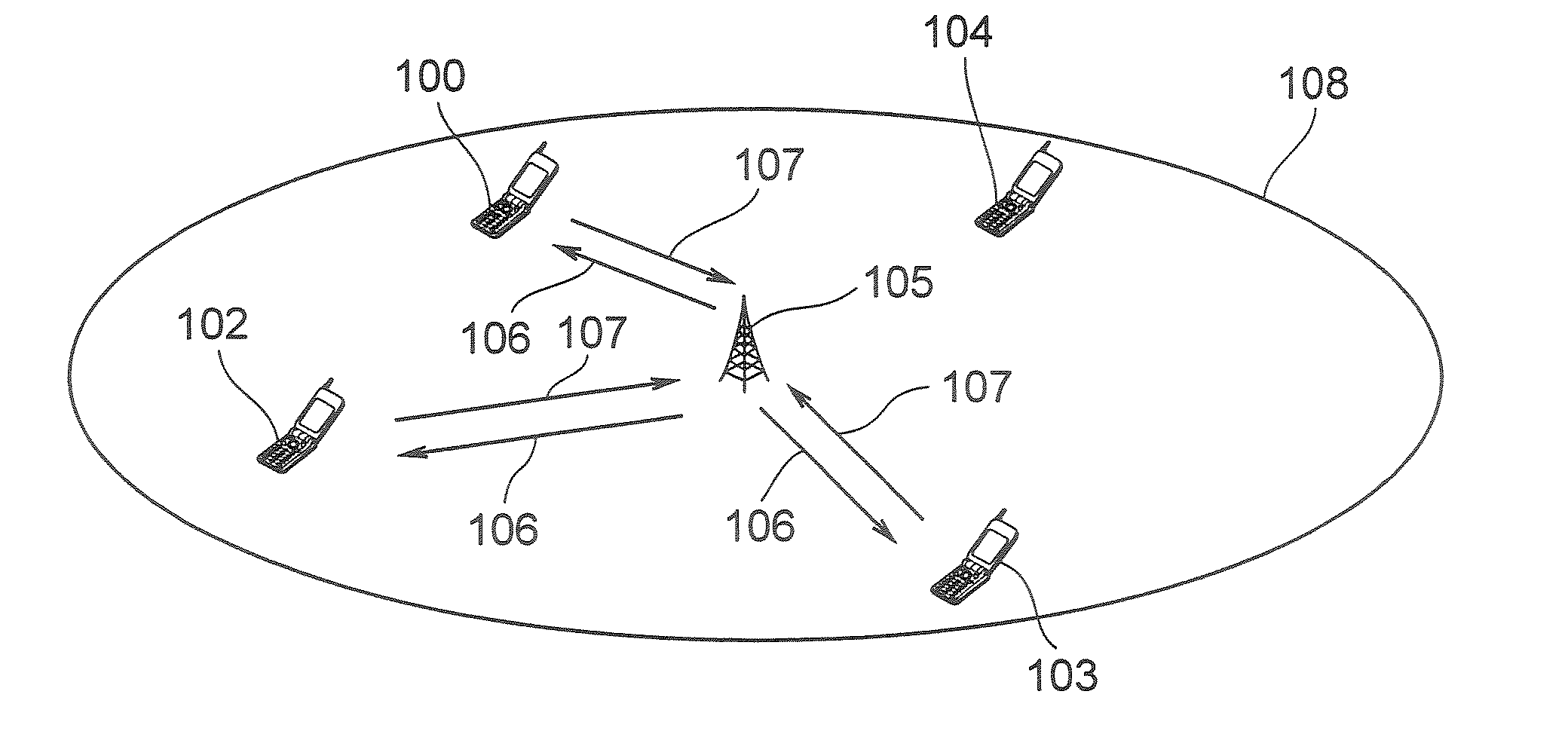
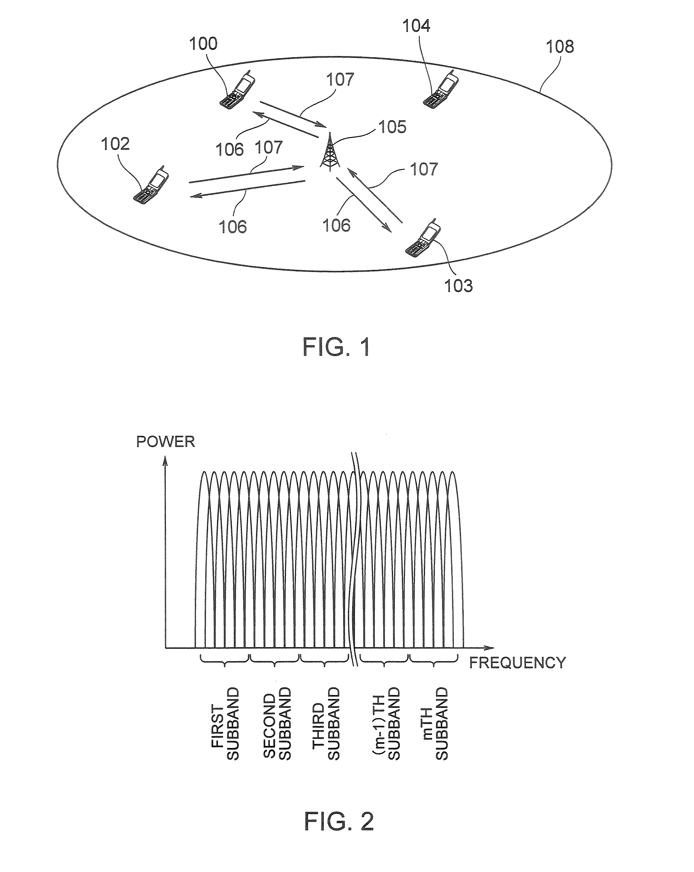
[0043]FIG. 1 shows an example of a radio communication system according to this embodiment. This radio communication system includes a base station 105 and a plurality of radio terminals (hereinafter simply referred to as “terminals”) 101, 102, 103, 104. The terminal 101, terminal 102, terminal 103 and terminal 104 are located within reach of radio signals from the base station 105, that is, within a communication area (cell) 108.

[0044]Radio signal transmission from the base station 105 to the respective terminals 101 to 104 is called a “downlink 106” and radio signal transmission from the respective terminals 101 to 104 to the base station 105 is called an “uplink 107.”

[0045]A multicarrier communication scheme such as OFDM (Orthogonal Frequency Division Multiplexing) or multicarrier CDMA (Code Division Multiple Access) is used for the downlink 106. In a multicarrier communication, communication is carried out using a plurality of subcarriers arranged on a frequency axis. An OFDM co...

second embodiment

[0109]In a second embodiment, scheduling using a scheduling table will be described in detail though some parts of explanations overlap the explanations of the first embodiment.

[0110]As in the case of the first embodiment, suppose an OFDMA (Orthogonal Frequency Division Multiple Access) communication as shown in FIG. 7 whereby communication is carried out using m subbands obtained by dividing an OFDM subcarrier group into the plural. Suppose that the transmission path is temporally divided into frames and the current time point corresponds to an nth frame. Furthermore, as shown in the scheduling table in FIG. 8, suppose data under QoS control directed to a terminal X is being sent in a first subband from the base station during transmission in the current nth frame and the transmission of this data under QoS control is completed in the nth frame. Furthermore, suppose data under QoS control directed to a terminal B is being sent in an (m−1)th subband of the nth frame from the base st...

third embodiment

[0117]A third embodiment is characterized by adding information indicating a degree of importance of transmission data to an assigned flag. Hereinafter, this embodiment will be explained in detail.

[0118]As data transmitted from a base station to each terminal, there are data having a high degree of importance, interruption of transmission of which is hardly allowed or data having a low degree of importance, interruption of transmission of which may be allowed if necessary. Thus, the base station assigns not only an assigned flag but also information indicating a degree of importance of data carried by the subband to which data under QoS control is assigned, to the subband. That is, the degree of importance is included in an assignment status signal indicating that assignment is already completed. The degree of importance may have two values so as to be described with 1 bit, but by using a plurality of bits to express the degree of importance with multivalues, the degree of importanc...


PUM


Abstract

According to an aspect of the present invention, there is provided with a base station which communicates with radio terminals through time frames for transmission by using a plurality of frequency channels, including: a reception section configured to receive communication quality information indicating communication quality of one or more frequency channels from each the radio terminal; a scheduling section configured to schedule frequency channels to be assigned to the respective radio terminals based on the communication quality information received from the respective radio terminals; a signal generation section configured to generate assignment status signals indicating whether or not respective frequency channels are already assigned in a second time frame next to a first time frame; and a reporting section configured to report the assignment status signals for the frequency channels to each the radio terminal through the first time frame

Description

CROSS-REFERENCE TO RELATED APPLICATIONS[0001]This application is based upon and claims the benefit of priority from the prior Japanese Patent Applications No. 2006-94392 filed on Mar. 30, 2006, the entire contents of which are incorporated herein by reference.BACKGROUND OF THE INVENTION[0002]1. Field of the Invention[0003]The present invention relates to a base station, radio terminal and radio communication method.[0004]2. Related Art[0005]A communication scheme such as OFDM (Orthogonal Frequency Division Multiplexing) communication scheme or multicarrier CDMA (Code Division Multiple Access) communication scheme is attracting attention in recent years. In these communication schemes, digital signals are transmitted / received by being mapped to a plurality of subcarriers over wider bandwidth. These communication schemes make it possible to increase transmission rate and improve resistance to frequency selective fading. On the other hand, OFDMA (Orthogonal Frequency Division Multiple ...

Claims


Application Information

Patent Timeline
IPC IPC(8): H04Q7/00H04W72/08
CPCH04W72/085H04W72/542
Inventor SAKATA, REN
Owner KK TOSHIBA
Why Eureka
Try Eureka