Rotary anode X-ray tube device
a rotary anode and x-ray tube technology, which is applied in the direction of x-ray tube windows, electrical discharge tubes, electrical apparatuses, etc., can solve the problems of non-uniformity of x-rays outputted from the rotary anode x-ray tube devi
- Summary
- Abstract
- Description
- Claims
- Application Information
AI Technical Summary
Benefits of technology
Problems solved by technology
Method used
Image

Examples
first embodiment
[0029] First, the first embodiment will be described in detail referring to FIGS. 1 and 2.
[0030] [Configuration of Rotary Anode X-ray Tube Device]
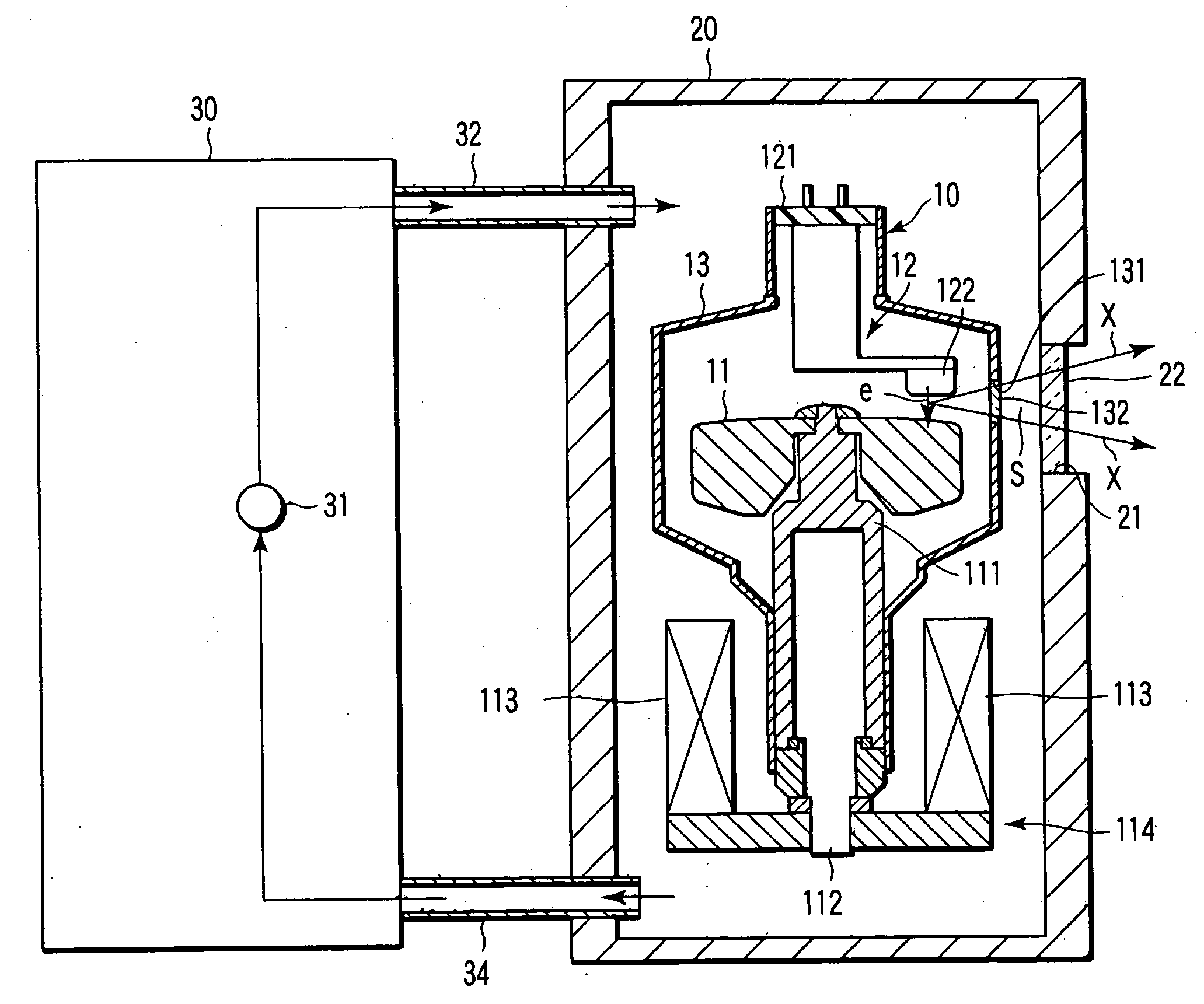
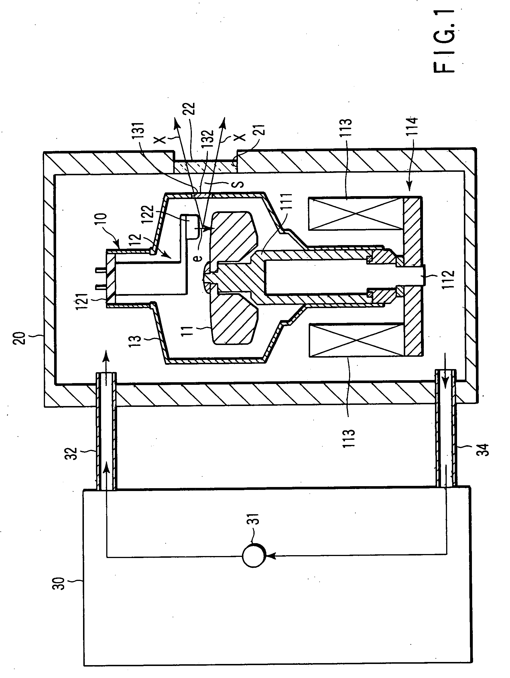
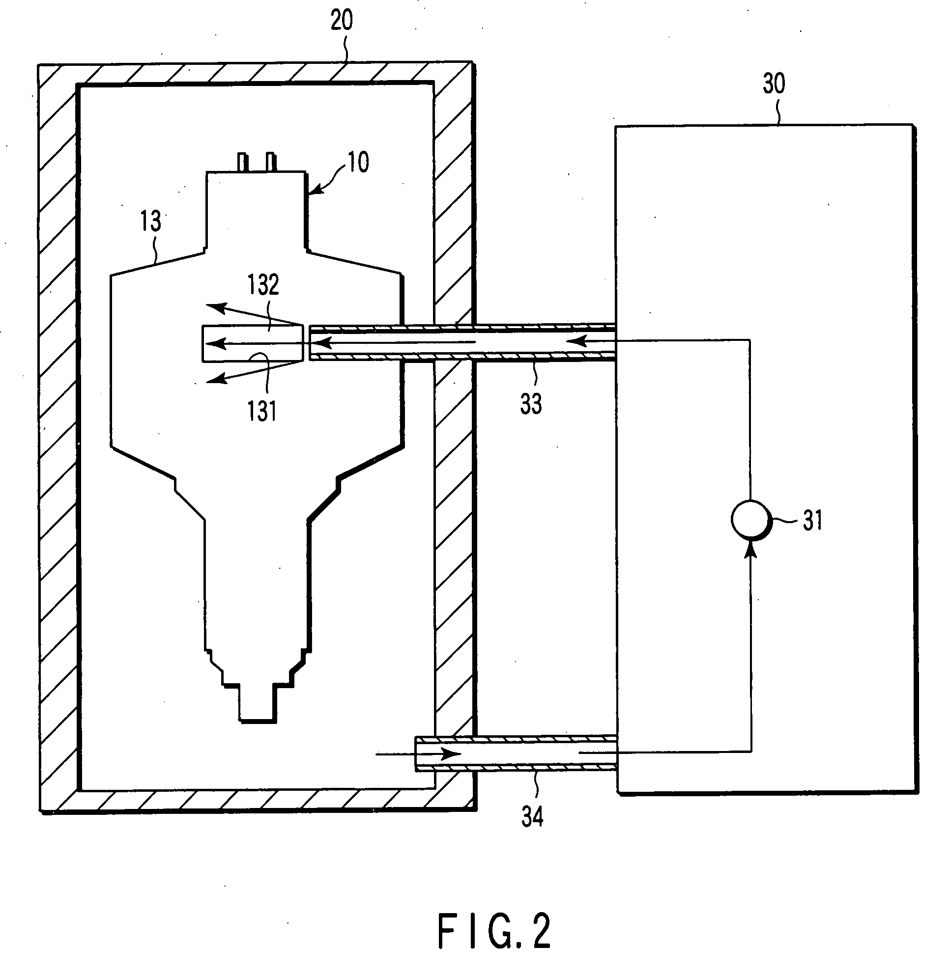
[0031]FIG. 1 is a sectional view of a rotary anode X-ray tube device in a first embodiment of the present invention; and FIG. 2 is a sectional view of the rotary anode X-ray tube device in the same embodiment.
[0032] As shown in FIG. 1, the rotary anode X-ray tube device in the present embodiment is mounted on equipment such as an X-ray image diagnosing apparatus represented by an X-ray computerized tomographic imaging apparatus or a nondestructive inspection apparatus. This X-ray tube device is composed of: an X-ray tube 10 for radiating X-rays; a housing 20 for housing the X-ray tube 10, the housing being filled with a cooling liquid for cooling the X-ray tube 10; and a circulation pump 30 connected to the housing 20, the circulation pump circulating the cooling liquid filled in the housing 20. As a cooling liquid, a non-oil based cooli...
second embodiment
[0057]FIG. 3 is a sectional view of a rotary anode X-ray tube device in a second embodiment of the present invention.
[0058] As shown in FIG. 3, the rotary anode X-ray tube device in the present embodiment is different from that in the first embodiment in that two diffusion restriction plates 50 are added. These diffusion restriction plates 50 sandwich a gap area between an X-ray output window 132 and an X-ray transmission window 22 at both sides in a transverse direction of the X-ray output window 132 and the X-ray transmission window 22, in a gap S between an X-ray tube 10 and a housing 20.
[0059] In this manner, a cooling liquid ejected from a subsidiary ejection pipe 33 flows along the two diffusion restriction plates 50, whereby the cooling liquid does not diffuse in the transverse direction of the X-ray output window 132 and the X-ray transmission window 22. Therefore, the flow of the cooling liquid is efficiently formed in the gap S between the X-ray output window 132 and the...
third embodiment
[0061]FIG. 4 is a sectional view of a rotary anode X-ray tube device in a third embodiment of the present invention.
[0062] As shown in FIG. 4, the rotary anode X-ray tube device in the present embodiment is different from that in the first embodiment in that a diffusion restriction frame 60 and a collection pipe 61 are added.
[0063] The diffusion restriction frame 60 is disposed in a gap S between an X-ray tube 10 and a housing 20 so as to surround a gap area between an X-ray output window 132 and an X-ray transmission window 22. Openings 603 and 604 are formed respectively at wall portions 601 and 602 disposed at both sides in a longitudinal direction of the X-ray output window 132 and the X-ray transmission window 22. A subsidiary ejection pipe 33 connected to a circulation pump 30 penetrates the housing 20 and is connected to the opening 603 of the diffusion restriction frame 60.
[0064] The collection pipe 61 is connected to the opening 604 of the diffusion restriction frame 60 ...
PUM
 Abstract
Description
Claims
Application Information