Acoustic fluid machine

a technology actuator, which is applied in the direction of positive displacement liquid engine, piston pump, liquid fuel engine, etc., can solve the problems of leakage of the portion, poor performance of acoustic fluid machine, and inability to use, so as to increase the load of the actuator as a sound-driving sour

Inactive Publication Date: 2007-10-11
ANEST IWATA CORP
View PDF10 Cites 4 Cited by
  • Summary
  • Abstract
  • Description
  • Claims
  • Application Information

AI Technical Summary

Problems solved by technology

However, in a usual acoustic fluid machine, as the amplitude of the seal ring is about 100-500 μm and the piston performs very small reciprocations at about 1000 times a second, only a certain portion of the seal ring bumps and wears locally, resulting in a leakage from the portion.
Therefore, the acoustic fluid machine performs badly and can not be used.
The seal ring inherently has frictional resistance, and ...

Method used


Image

  • Acoustic fluid machine
  • Acoustic fluid machine
  • Acoustic fluid machine

Examples


second embodiment

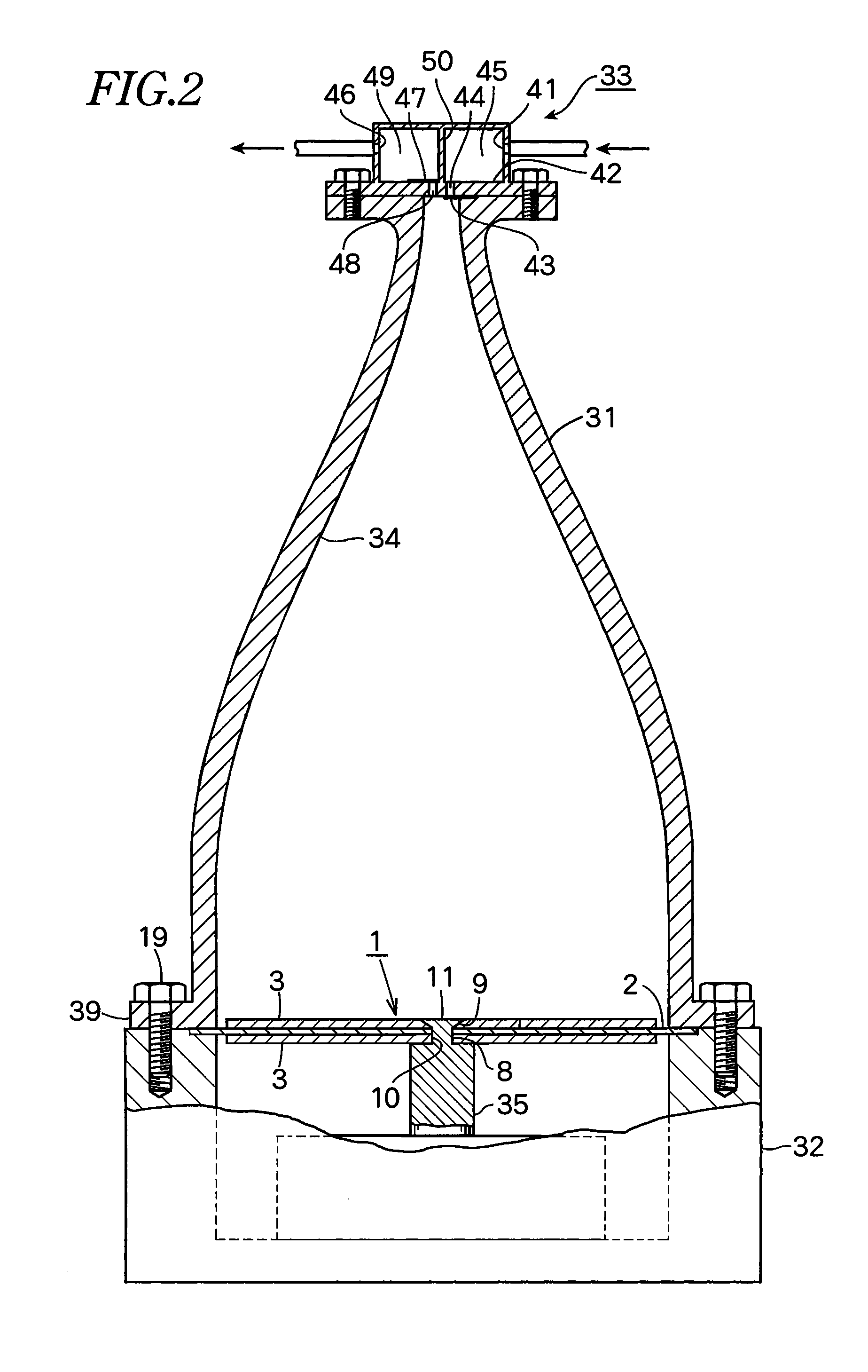
[0034]In the second embodiment in FIG. 2, a reciprocation vibrating rod 35 has smaller-diameter portion 8 at the upper portion and a flat head portion 11. The smaller-diameter portion 8 is inserted into an attachment hole 10 of the piston 1 which has a countersink 9 formed on the hole 10 at the center of the piston 1 from a bottom, and the upper end of the smaller-diameter portion 8 is calked to form the flat head portion 11 which closes the countersink 9.

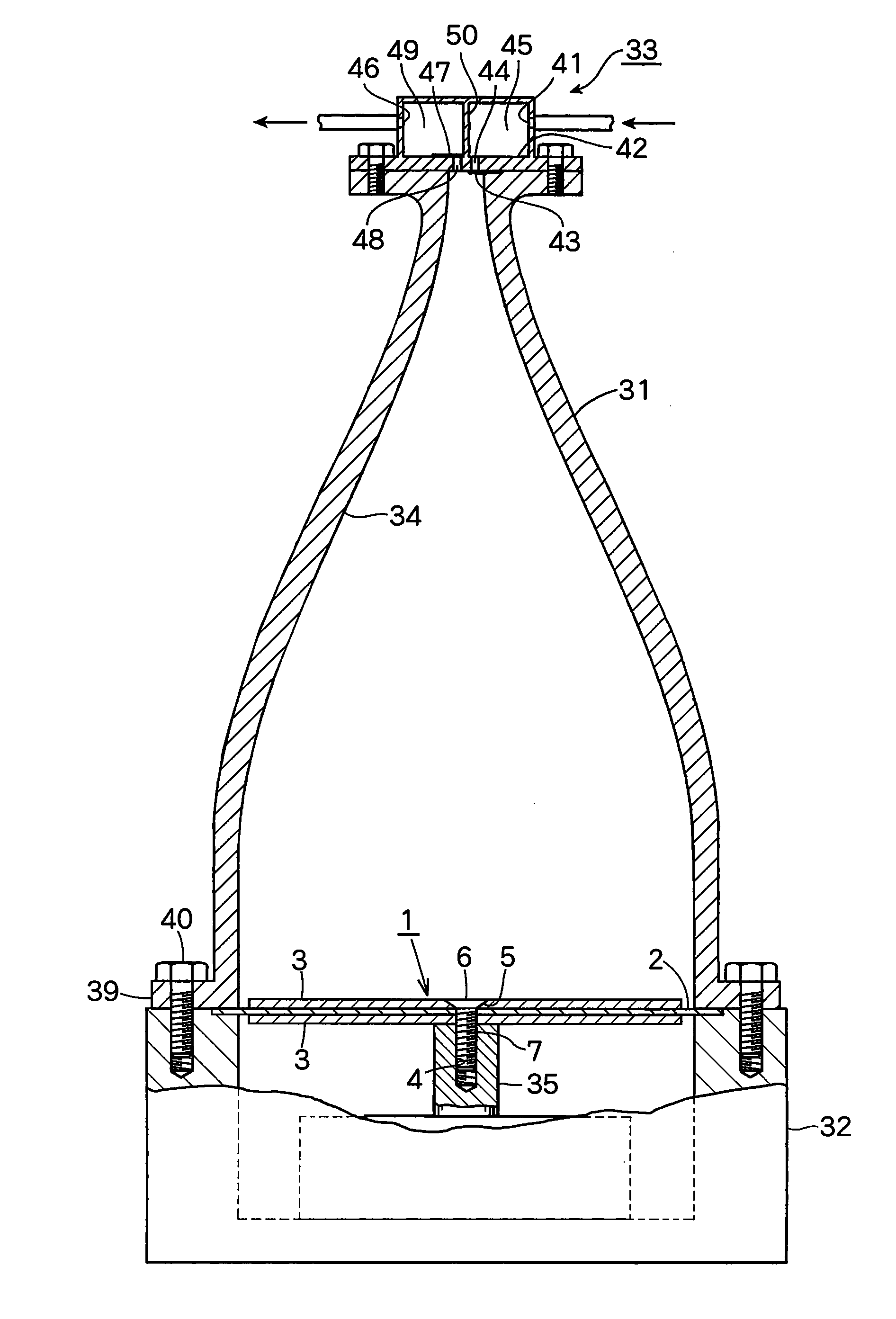
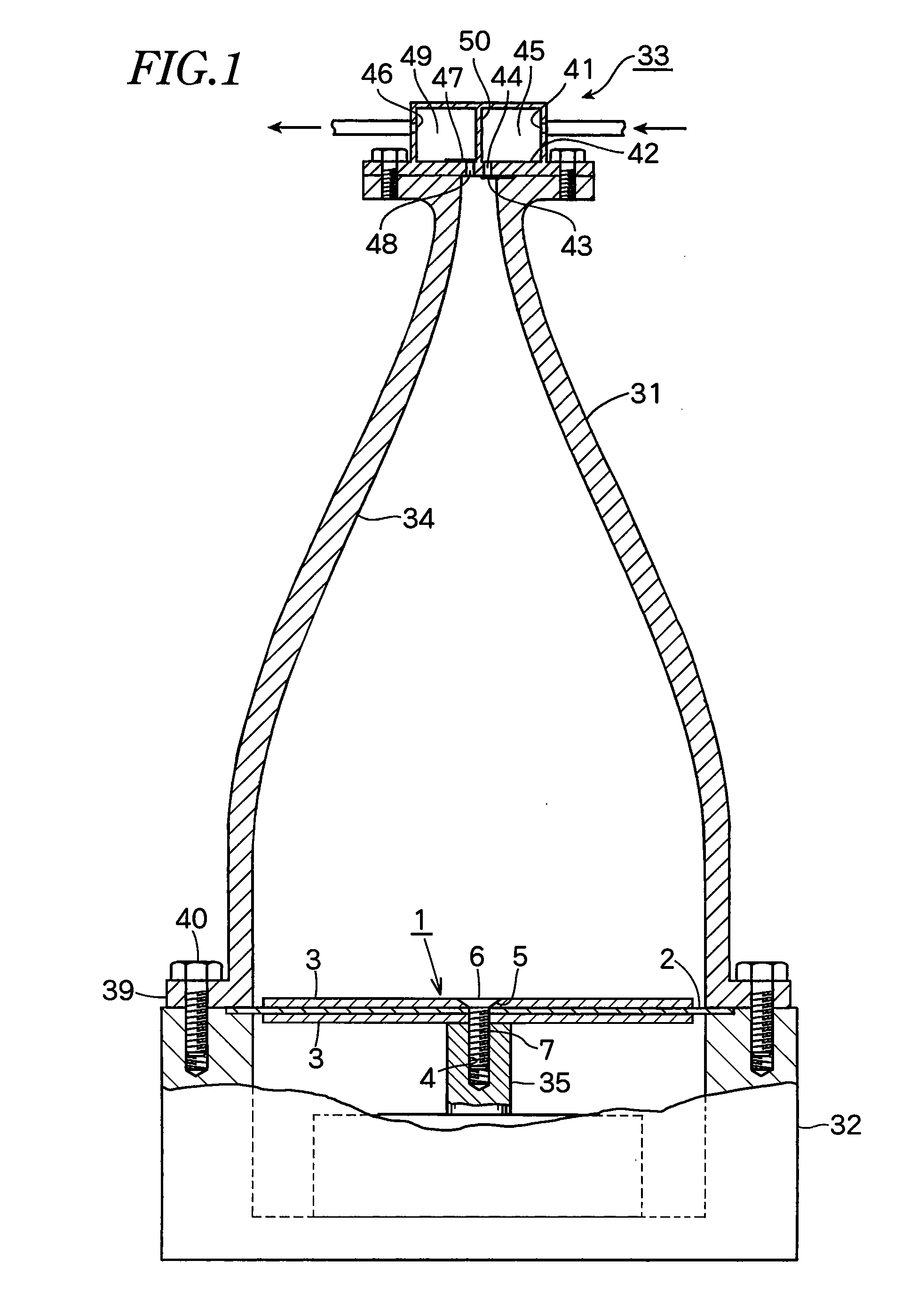
[0035]In both cases, the upper surface of the flat head screw 6 or the flat head portion 11 is completely coplanar with the upper surface of the piston 1.

third embodiment

[0036]FIG. 3 shows the present invention in which a flat metal plate 3 which is smaller in diameter than a rubber plate 2 is embedded in the rubber plate 2.

fourth embodiment

[0037]FIG. 4 shows the present invention in which the circumference of the metal plate 3 is fitted between a rubber plate 2 and an inward flange 2a which is smaller in diameter than the rubber plate 2.


PUM


Abstract

In an acoustic fluid machine, an acoustic resonator gradually reduces in diameter towards the top on which a valve device is provided to suck a gas into the resonator. The gas is compressed in the resonator by a circular-plate piston at the lower end of the resonator and discharged via an outlet of the valve device. The piston comprises a rubber plate fixed to the resonator and a metal plate attached on the rubber plate.

Description

BACKGROUND OF THE INVENTION[0001]The present invention relates to an acoustic fluid machine, the machine utilizing fluctuations in pressure amplitude based on acoustic resonance.[0002]In JP2006-266202A, there is an acoustic fluid machine in which a vibrating plate which reciprocates at high speed axially with a very small amplitude by driving sound source is provided on the inside of a larger-diameter base of an acoustic resonator, and a gas is taken into the acoustic resonator and discharged therefrom via a smaller-diameter upper end by virtue of pressure fluctuations within the acoustic resonator by reciprocation of the vibrating plate.[0003]This acoustic fluid machine utilizes fluctuations in the pressure amplitude of standing acoustic waves generated by the phenomenon of resonance of a gas column inside the resonator by the piston when the piston is made to reciprocate axially with a very small amplitude, and comprises as an operating part only an actuator that reciprocates vibr...

Claims


Application Information

Patent Timeline
IPC IPC(8): F01N1/14
CPCF04B35/00
Inventor HOSSAIN, MOHAMMED ANWAR
Owner ANEST IWATA CORP
Why Eureka
Try Eureka