Tape dispenser

a dispenser and tape technology, applied in the direction of thin material handling, metal-working equipment, metal-working equipment, etc., can solve the problems of increasing optimizing the size of the package, and the cost of such packaging, so as to promote compactness and efficiency, the effect of reducing the cost of purchasing a plurality and overcoming the foregoing

Inactive Publication Date: 2007-10-11
HENKEL CORP
View PDF14 Cites 12 Cited by
  • Summary
  • Abstract
  • Description
  • Claims
  • Application Information

AI Technical Summary

Benefits of technology

[0003] In accordance with the present invention, a tape dispenser is provided which minimizes or overcomes the foregoing and other problems and disadvantages associated with tape dispensers heretofore available. In this respect, for example, tape dispensers in accordance with the present invention are structured for an interengaging relationship which promotes compactness and efficiency with respect to the packaging thereof and for a tandem interrelationship therebetween, if desired, in connection with their use in a given work area. More particularly in this respect, the hub of a tape dispenser in accordance with the invention includes a portion extending beyond the confines of a dispenser with respect to a roll of tape thereon for mating interengagement with a hub portion of a second dispenser of like construction, whereby a nested relationship is provided which promotes compactness in connection with packaging of a plurality of dispensers such as by shrink wrapping. Moreover, the interengaging relationship provides for the selective use of two or more dispensers in the interengaged relationship which advantageously maintains the dispensers in a common area of use in a work area such as a desk or the like. Preferably, the structures of the dispensers promotes the joining of two or more dispensers with a desired alignment therebetween, thus promoting efficiency with respect to the combining of two or more dispensers either for packaging and / or use thereof in a tandem relationship.
[0004] In accordance with another aspect of the invention, a radially elongated tape guide surface is provided to promote adherence of the distal end of a tape being dispensed to the guide so as to minimize the undesired displacement of the distal end back onto the tape roll following a dispensing operation. In accordance with yet another aspect of the invention, the tape guide is provided with inwardly extending recesses along the opposite sides thereof which facilitate engagement of the fingers of a user with the tape to initiate a dispensing operation.
[0005] It is accordingly an outstanding object of the present invention to provide improvements in the structure of dispensers for rolls of tape which promote compactness and efficiency in connection with the packaging and use of the tape dispensers.
[0006] Another object of the invention is the provision of a tape dispenser of the foregoing character which is structured for a plurality of the dispensers to be releasably interengaged in a manner which promotes compactness of a plurality of the dispensers in connection with the packaging thereof and which, optionally, provides for a plurality of the dispensers to be maintained in a tandem relationship during use.
[0007] Still another object is the provision of a tape dispenser of the foregoing character wherein alignment of adjacent dispensers during interengagement therebetween promotes the efficiency of an assembly of a plurality of the dispensers and maintaining such alignment for packaging and / or use purposes.
[0008] Yet another object is to provide a dispenser of the foregoing character with an improved tape guide structure which optimizes surface contact with respect to the distal end of tape to be dispensed and which promotes ease of access to the distal end for dispensing the tape from the roll.

Problems solved by technology

Moreover, it is not uncommon for a user of such tape dispensers to have a plurality of dispensers in a use location such as a desk and, heretofore, such a plurality of dispensers are disassociated with one another in the area of use which can be inconvenient if not annoying to the user.
Further, such dispensers heretofore available are generally individually packaged which adds to the expense of purchasing a plurality of the dispensers at a given time.
Even if a plurality of such dispensers should be offered in a single package, the orientation of the dispensers relative to one another in the package is not conducive to optimizing the size of the package and, therefore, the cost of such packaging.

Method used


Image

  • Tape dispenser
  • Tape dispenser
  • Tape dispenser

Examples


Embodiment Construction

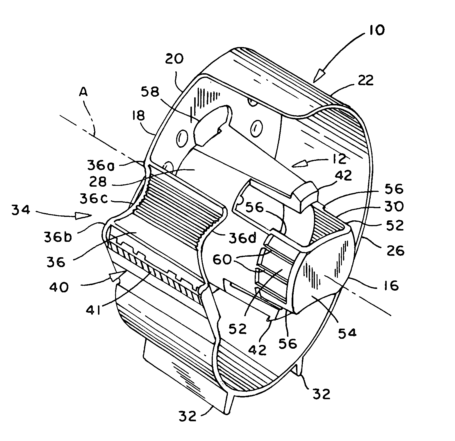
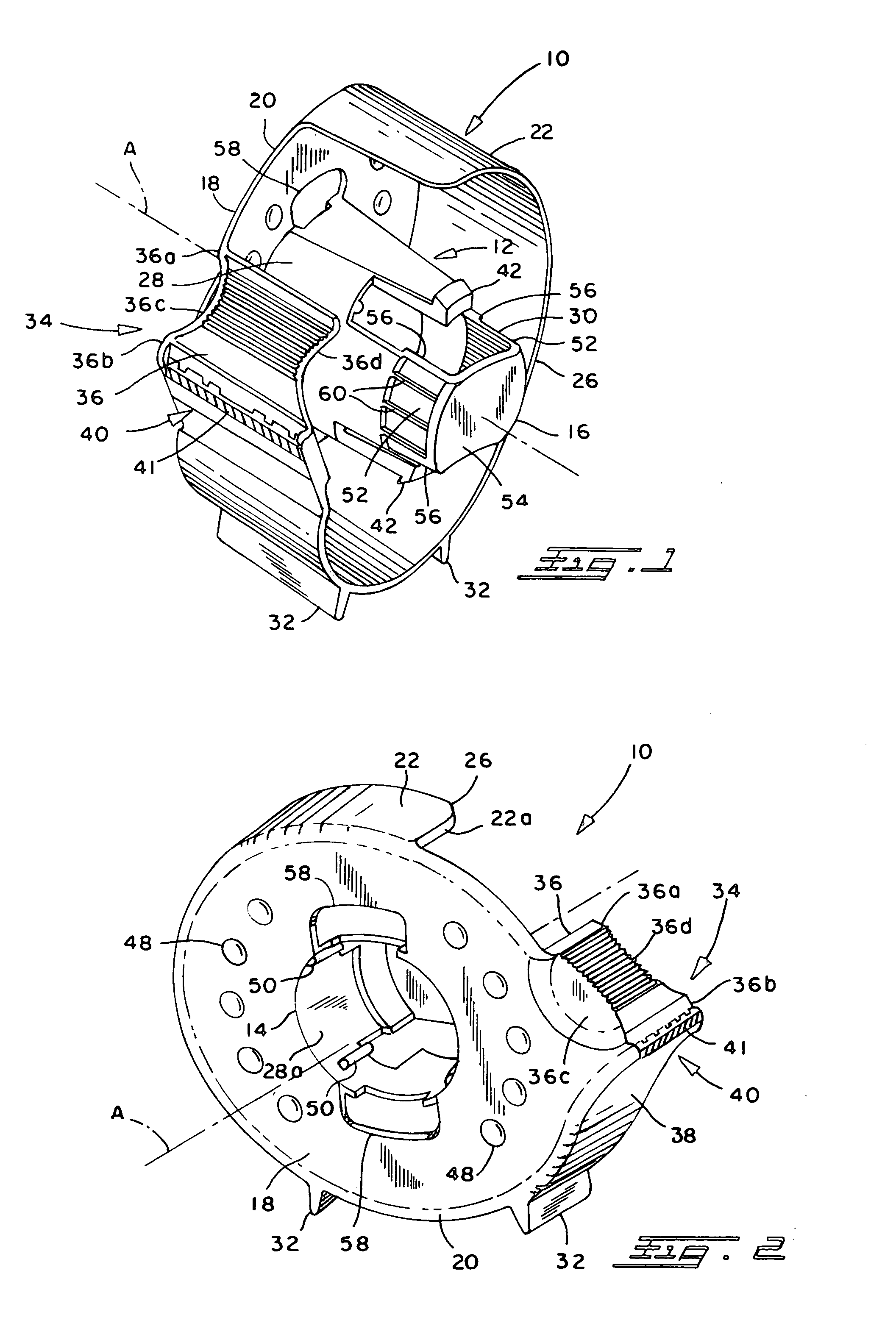
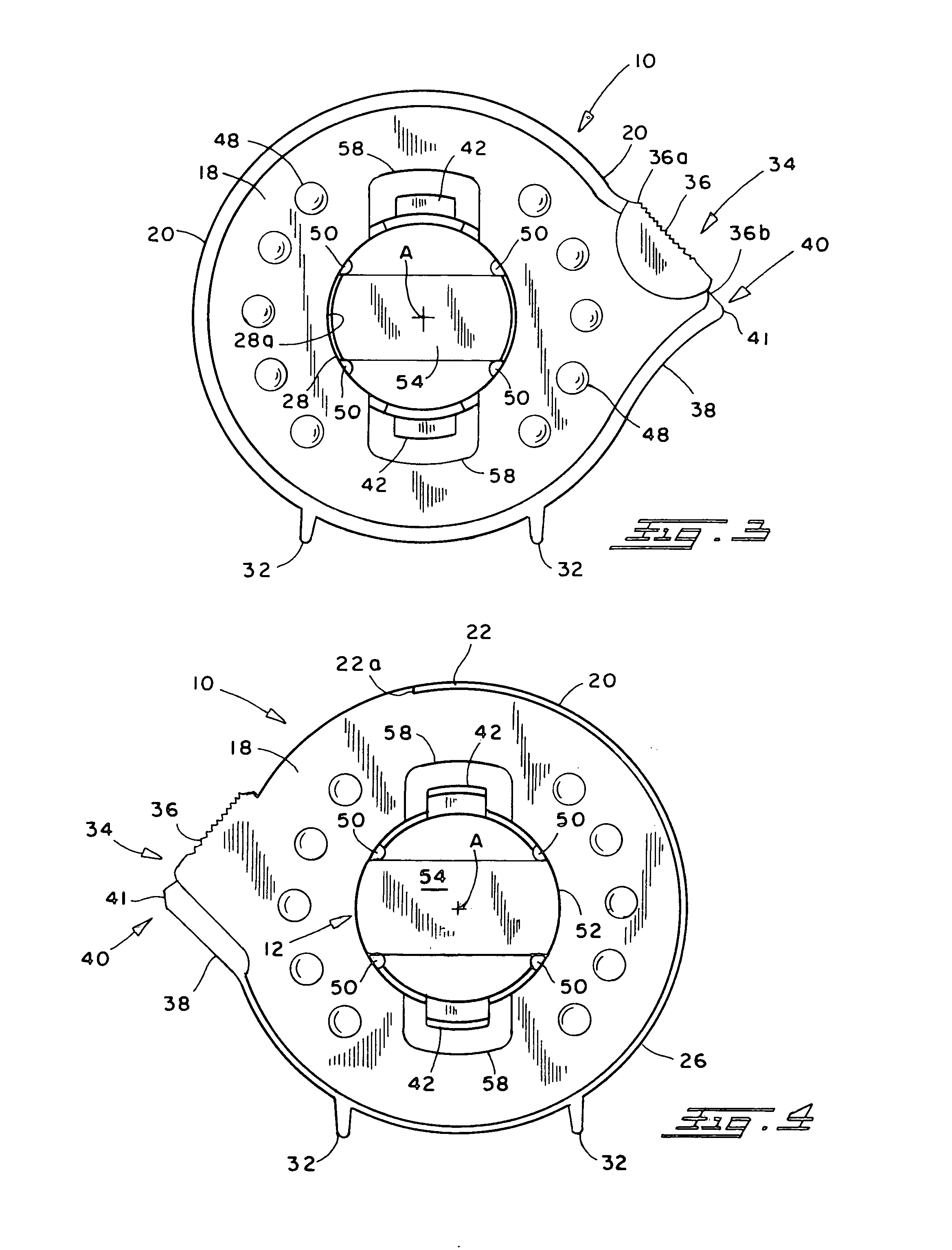
[0015] Referring now in greater detail to the drawings, wherein the showings are for the purpose of illustrating a preferred embodiment of the invention only and not for the purpose of limiting the invention, a tape dispenser 10 in accordance with the invention, as shown in FIGS. 1-4 of the drawing, is a one-piece construction, preferably of a plastic material, and comprises a tubular hub 12 having an axis A and axially opposite first and second ends 14 and 16, respectively. Dispenser 10 further includes a first wall 18 at end 14 of hub 12 and which extends radially outwardly from the periphery of the hub and has a peripheral outer edge 20, and a second wall 22 radially spaced from hub 12 and extending axially from wall 18 and, preferably, from peripheral edge 20, in the direction toward second end 16 of the hub. Wall 22 is parallel to axis A and has a circumferentially extending axially outer end or edge 26 between ends 14 and 16 of the hub. The latter relationship provides for hub...


PUM


Abstract

A tape dispenser has a tubular hub for receiving a roll of tape, and the hub has an axis and axially spaced first and second ends. A first wall extends radially outwardly of the hub at the first end, and a second wall is radially spaced from the hub and extends axially from the first wall the direction toward the second end of said hub. The hub includes a portion extending axially outwardly of the outer end of the second wall, and the first end and the latter portion of the hub are contoured for the first end of one tape dispenser to axially receive the portion of the hub of a second tape dispenser to interengage the two dispensers.

Description

BACKGROUND OF THE INVENTION [0001] This invention relates to the art of dispensers for rolls of tape and, more particularly, to improvements in connection with the packaging and / or use of such dispensers. [0002] Dispensers for rolls of tape such as cellophane tape, for example, are of course well known. Basically, such a dispenser includes a hub for rotatably supporting a roll of tape to be dispensed and, generally, a wall which circumferentially encompasses a roll of tape on the hub. Such a dispenser includes a tape guide radially spaced from the axis of the hub and which includes a serrated cutting edge for severing a portion of tape from the roll. Most often, the dispenser is made of a plastic material, and the cutting edge is either integral therewith or in the form of a metal blade attached to the tape guide. Often, the tape guide provides a radially narrow surface whereby, following severance of a length of tape from the roll, the trailing edge releases from the tape guide and...

Claims


Application Information

Patent Timeline
Patent Type & Authority Applications(United States)
IPC IPC(8): B26F3/02
CPCB65H35/0026B65H2402/10B65H35/0073Y10T225/238Y10T225/247Y10T225/257
Inventor FORAN, KENNETH C.CASTEEL, STEPHEN P.HAWLEY, JAMES K.VULPITTA, BRIAN A.CHUPA, KRISTENORTIZ, VANESSAVANDENBOSSCHE, SUZANNE P.
Owner HENKEL CORP
Why Eureka
Try Eureka