Viscoelastic liquid flow splitter and methods

Inactive Publication Date: 2007-10-11
HEWLETT PACKARD DEV CO LP
View PDF11 Cites 26 Cited by
  • Summary
  • Abstract
  • Description
  • Claims
  • Application Information

AI Technical Summary

Problems solved by technology

This can result in changes in the volume of material dispensed over time.
An example of this type of problem is in the encapsulation of integrated circuits where typically a two-part epoxy is premixed by the epoxy manufacturer and frozen.
In addition, typically, there are also problems relating to the entrapment of air within the liquid to be dispensed because small gas bubbles in the liquid compress, causing sputtering and inaccuracies in the volume of material dispensed.
Due to the viscoelastic behavior of most adhesives, controlling the dispense rate and dispense end point when dispensing a bead may be difficult.
Static mixers can deliver flow rates in the micro-liter per second range, but typically not with the same accuracy as a positive displacement type pump.
Generally, the accurate dispensing of viscoelastic fluids is made even more difficult as the distanc

Method used


Image

  • Viscoelastic liquid flow splitter and methods
  • Viscoelastic liquid flow splitter and methods
  • Viscoelastic liquid flow splitter and methods

Examples


Embodiment Construction

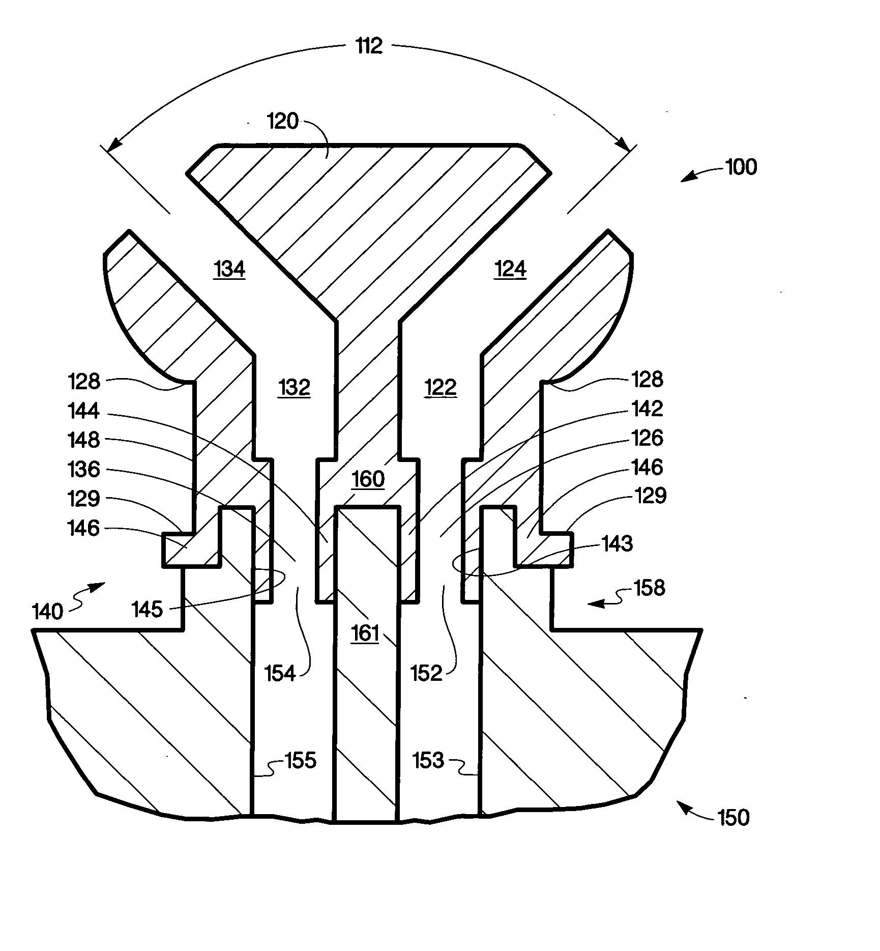
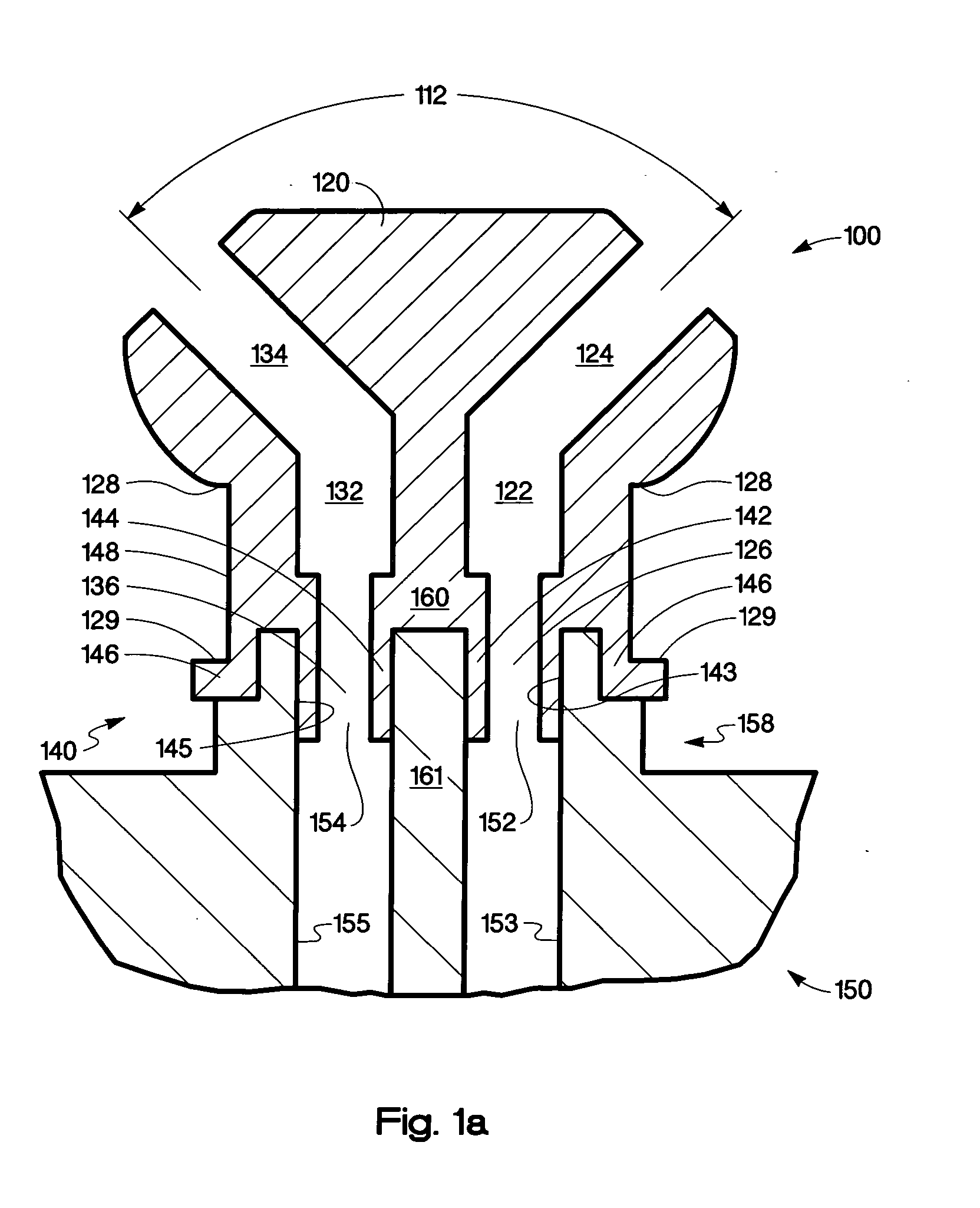
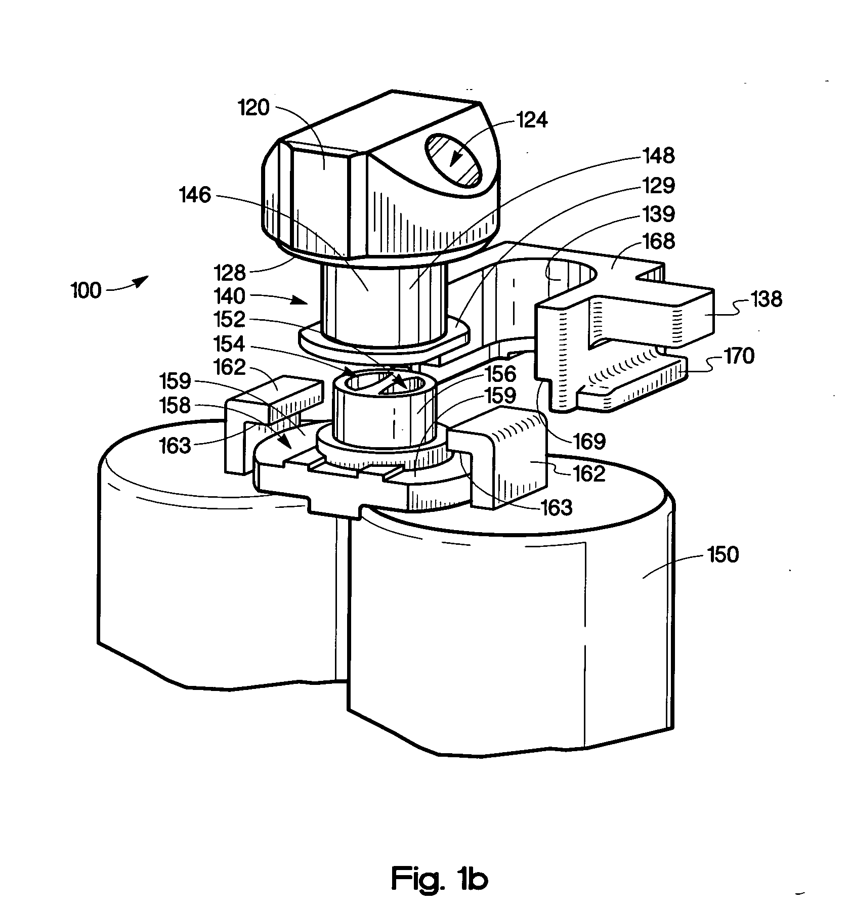
[0019] The present invention advantageously utilizes a viscoelastic liquid flow splitter, as part of a dispensing apparatus, to dispense quantities of a viscoelastic fluid of a precise volume. The viscoelastic liquid flow splitter is a device that keeps two reactive components separated as the two components are discharged from a storage container having multiple compartments. For example, a two-part adhesive such as a two part epoxy is stored in a double-barreled syringe where the epoxy resin is stored in one barrel or compartment and the hardener is stored in a second barrel or compartment. In addition, the dispensing apparatus may include at least two input channels feeding into a dispenser chamber having at least one feed screw, also commonly referred to as an auger, to both mix the components and dispense the liquid product. The viscoelastic liquid flow splitter keeps the two components separated until they are mixed and dispensed in a substantially simultaneous manner, thereby...


PUM


Abstract

A viscoelastic liquid flow splitter includes a flow splitter body having a first bore including a first bore outlet and a first bore inlet, and a second bore including a second bore outlet and a second bore inlet The bore inlets are substantially parallel to each other and the bore outlets diverge from each other at an angle. The flow splitter also includes a compression fitting having a first and a second tubular portion fluidically coupled to the first and second bore inlets where the tubular portions are configured to fluidically couple to a double barreled viscoelastic liquid dispensing syringe.

Description

BACKGROUND Description of the Art [0001] The ability to dispense a precise quantity of liquid such as an adhesive, a lubricant, a conductive epoxy, a solder paste, or various other fluids at precise locations on a surface is important to a number of manufacturing processes, especially in the electronics, medical, automotive, and aerospace industries. The assembly of circuit boards, hard disk drives, inkjet cartridges, flat panel displays, cell phones, personal digital assistants, medical devices, sensors, motors, and pumps are just a few examples of manufactured products that utilize such processes. During normal operation, it is desirable to achieve and maintain high repeatability in the dispensing quantity in spite of variations in temperature, viscosity, or both. [0002] For some applications, the liquid dispensed is extremely sensitive to such variations, this is especially true where the dispensed liquid has a relatively high viscosity which itself varies as the temperature chan...

Claims


Application Information

Patent Timeline
IPC IPC(8): G06K19/06
CPCB01F7/246B01F7/248B05C17/0146B05C17/00566B05C17/00569B05C17/00553B01F27/9213B01F27/923
Inventor STRECKER, TIMOTHY D.WOODRUFF, MARK W.GARCIA, CARLOSCOLBURN, WILLIAM S.BREIDENTHAL, SCOTT
Owner HEWLETT PACKARD DEV CO LP
Why Eureka
Try Eureka