Woven fabric comprising leno weave bound metal

a technology of woven fabric and metal, which is applied in the field of woven fabric comprising metal elements, can solve the problems of fabric having fabric has the tendency to move in the unwinding direction, and the fabric has the tendency to run out of alignment, so as to prevent the possibility of fabric instability

Inactive Publication Date: 2007-10-11
NV BEKAERT SA
View PDF21 Cites 24 Cited by
  • Summary
  • Abstract
  • Description
  • Claims
  • Application Information

AI Technical Summary

Benefits of technology

[0008] The above-mentioned advantageous effects are realized by a woven fabric having the specific features set out in claim 1. Specific features for preferred embodiments are set out in the dependent claims.
[0009] The term “Leno weave” is to be understood as the binding of a weft element, also often identified as “filling”, to a warp element, due to the twisting of this warp element with a binding element. In order to obtain such bound, the binding element, running through the fabric in warp direction of the fabric, is present at a given side of the warp element to be bound to the weft element at an intersection point of this warp and weft element. Warp element and binding element are present at a first surface of the fabric, whereas the weft element to be bound is present at the opposite surface of the fabric. Following now the binding element in warp direction, the binding element crosses the warp element in a first direction and then traverse trough the fabric thickness towards the opposite side of the fabric. The binding element then crosses the weft element at the outer surface of the fabric. The binding element traverse again through the fabric to the same side of the warp element, and crosses the same warp element again, however in opposite direction as was previously the case, in order to go to the consecutive intersection where warps and wefts are bound by his binding element.
[0010] The effect is that weft and warp element are bound to each other due to crossing of the binding element in this order.
[0011] According to the present invention, at least a first set of binding elements cross more than one warp

Problems solved by technology

A first disadvantage of these fabrics is the possible instability of the fabric.
During production of the fabric, and during winding and unwinding, the fabric has the t

Method used


Image

  • Woven fabric comprising leno weave bound metal
  • Woven fabric comprising leno weave bound metal
  • Woven fabric comprising leno weave bound metal

Examples


Embodiment Construction

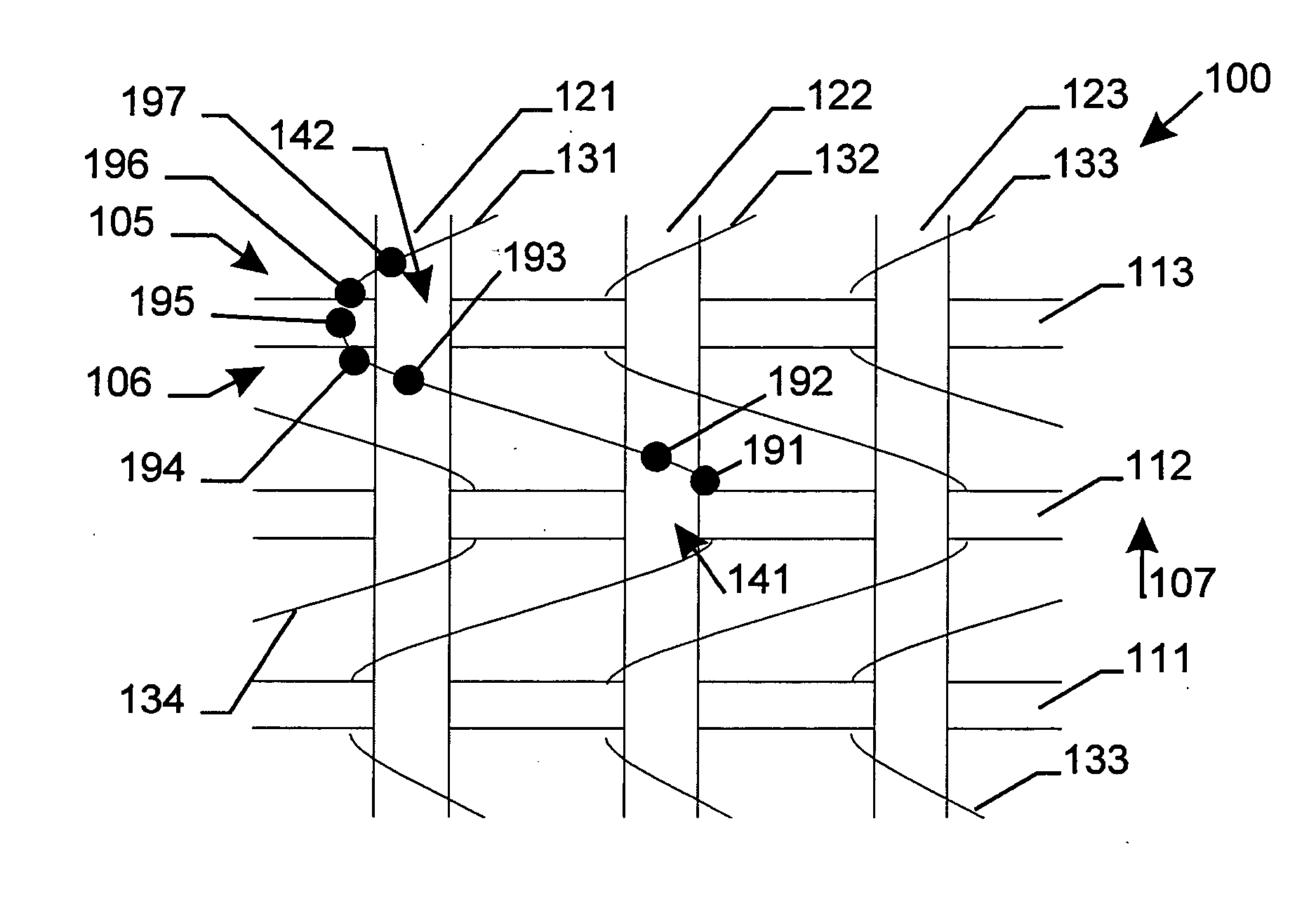
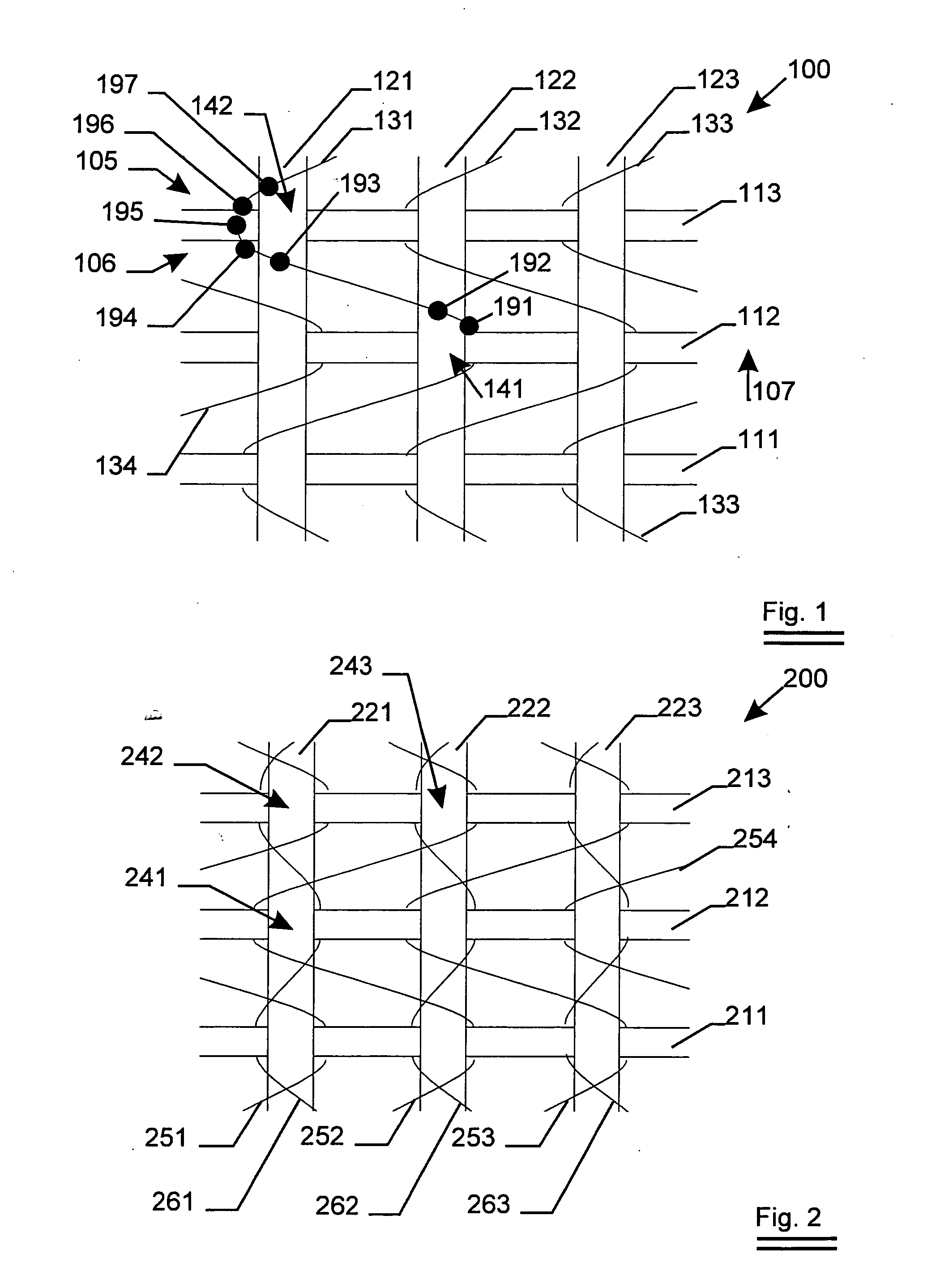
[0042] A woven fabric 100 as subject of the invention is shown in FIG. 1. The fabric 100 comprises weft elements (111, 112, 113) which are bound to warp elements (121, 122, 123) by means of one set of binding elements (131, 132, 133, 134) at each intersection point of a warp and a weft element.

[0043] At the intersection point 141, were warp element 122 and weft element 112 cross, the binding element 131 binds this warp and weft element. At the consecutive intersection point 142, further in the warp direction 107 of the woven fabric 100, this binding element binds weft element 113 and warp element 121.

[0044] At point 191 of the binding element 131, the binding element 131 is at the right side of first warp element 121 and second warp element 121. When following the binding element 131 in warp direction from point 191 onwards, the binding element 131 crosses warp elements 122 and 121 in this order in left direction at point 192 and 193. At point 194, the binding element 131, present...


PUM


Abstract

A woven fabric in which warp elements are provided out of metal. The fabric further comprising at least a first set of substantially parallel binding elements present in warp direction of the fabric. This first set of binding elements bind the warp elements to the weft elements by means of a leno weave at at least a part of the intersection points of warp and weft elements. The fabric as subject of the invention is characterized in that each binding element of the first set of binding elements crosses more than one warp element between consecutive intersection points bound by this binding element.

Description

FIELD OF THE INVENTION [0001] The present invention relates to a woven fabric comprising metal element such as steel cords, which woven fabric have warp elements and weft elements being bound to each other by means of a leno weave. BACKGROUND OF THE INVENTION [0002] Woven fabrics having warp elements and weft elements being bound to each other by means of a leno weave are known in the art. [0003] Such woven fabrics comprising metal elements such as steel cords are known from e.g. EP96929B1. [0004] The woven fabrics as described in EP96929B1 suffer however from several disadvantages. [0005] A first disadvantage of these fabrics is the possible instability of the fabric. During production of the fabric, and during winding and unwinding, the fabric has the tendency to run out of alignment. [0006] In order to prevent the fabric of curling, as shown in EP96929B1, adjacent warps having opposite directions of twisting are used. However, in case of metal cords, during production of the fabr...

Claims


Application Information

Patent Timeline
IPC IPC(8): B21F27/00
CPCB21F27/02Y10T442/3382Y10T442/339Y10T442/109
Inventor BRAEKEVELT, GEERTGALLENS, JEROENPUYPE, LODE
Owner NV BEKAERT SA
Why Eureka
Try Eureka