Backlight unit using light emitting diode

a technology of light-emitting diodes and backlight units, which is applied in the field of backlight units, can solve the problems of low color reproducibility, slow response rate, and inability to miniaturize an lcd panel, and achieve the effect of improving the image quality of the lcd panel

Inactive Publication Date: 2007-10-11
SAMSUNG ELECTRONICS CO LTD
View PDF13 Cites 39 Cited by
  • Summary
  • Abstract
  • Description
  • Claims
  • Application Information

AI Technical Summary

Benefits of technology

[0012]The present invention has been made to solve the foregoing problems of the prior art and therefore an aspect of the present invention is to provide a backlight unit using LEDs, in which LEDs in a plurality of LED modules are provided with driving current by a common driving circuit, decreasing the number of electronic components and the size of a driving board for mounting the electronic components and a regulated driving current is provided to all of the LED modules to allow uniform light emission of the LED modules, thereby improving the image quality of the LCD panel.

Problems solved by technology

A Cold Cathode Fluorescent Lamp (CCFL), which has been used as a light source for the existing LCD backlight unit, is prone to environmental pollution with use of mercury gas, slow in response rate, has low color reproducibility and is inappropriate for miniaturization of an LCD panel.
This increases the number of electronic components constituting the driving circuits, increasing the manufacturing costs of the backlight unit.
Therefore, different magnitudes of driving current are provided to the LEDs in the LED modules, which results in non-uniform light from the LED modules, degrading the image quality of the LCD panel.

Method used


Image

  • Backlight unit using light emitting diode
  • Backlight unit using light emitting diode
  • Backlight unit using light emitting diode

Examples


Embodiment Construction

[0020]Exemplary embodiments of the present invention will now be described in detail with reference to the accompanying drawings. The invention may however be embodied in many different forms and should not be construed as limited to the embodiments set forth herein. Rather, these embodiments are provided so that this disclosure will be thorough and complete, and will fully convey the scope of the invention to those skilled in the art. In the drawings, the shapes and dimensions may be exaggerated for clarity and the same reference numerals are used throughout to designate the same or similar components.

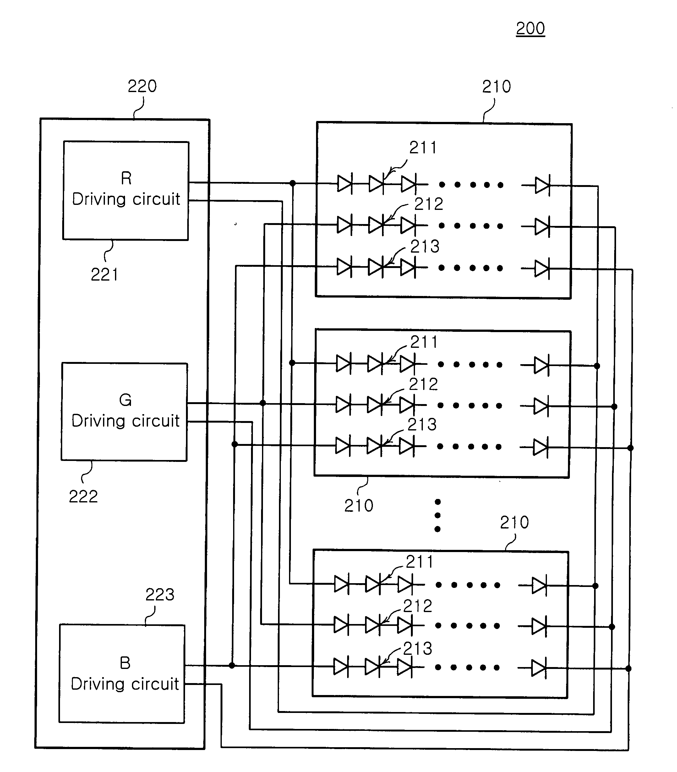
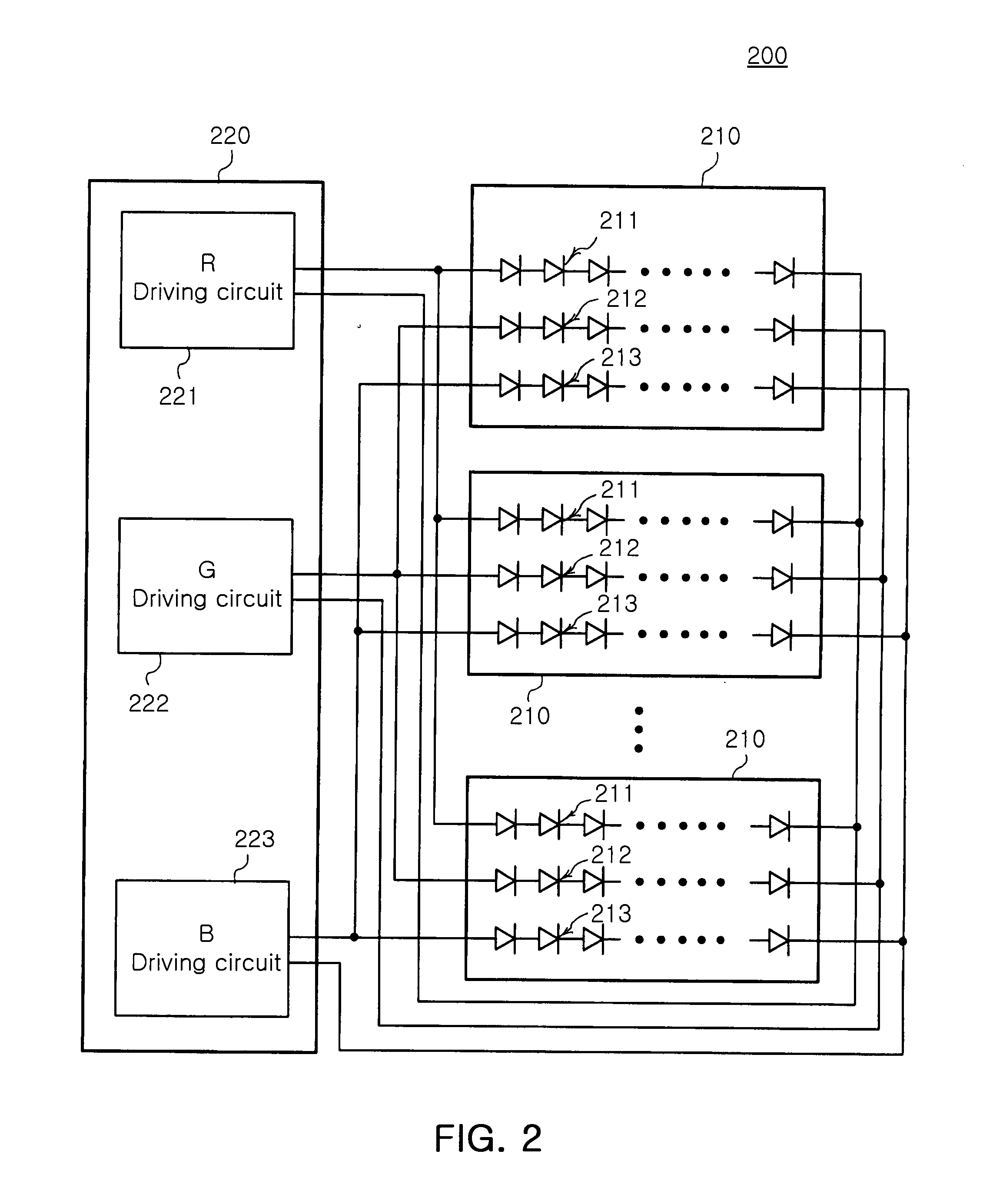
[0021]FIGS. 2 to 7 are views illustrating various embodiments of a backlight unit according to the present invention.

[0022]First, a backlight unit 200 according to an embodiment shown in FIG. 2 includes a plurality of LED modules 210 each composed of a plurality of red, green and blue LEDs, and a single LED driver 220 for driving the red, green and blue LEDs provided in each of the pl...


PUM

PropertyMeasurementUnit
coloraaaaaaaaaa
color reproducibilityaaaaaaaaaa
speedaaaaaaaaaa

Abstract

A backlight unit using LEDs in which a plurality of LEDs of different colors used for a surface light source are connected in an electric connection structure incorporating series and parallel connections so that the LEDs of the same color are driven by a single driving circuit, thereby improving the driving efficiency of LEDs. The backlight unit includes a plurality of LED modules each having a plurality of red LEDs, a plurality of green LEDs, and a plurality of blue LEDs electrically connected, respectively. The backlight unit also includes an LED driver composed of a red LED driving circuit, a green LED driving circuit, and a blue LED driving circuit for driving each color group of the plurality of LEDs provided in the LED modules. The plurality of red LEDs, the plurality of green LEDs, and the plurality of blue LEDs in the respective LED modules are electrically connected, respectively.

Description

CLAIM OF PRIORITY[0001]This application claims the benefit of Korean Patent Application No. 2006-0031891 filed on Apr. 7, 2006 and No. 2007-0017285 filed on Feb. 21, 2007 in the Korean Intellectual Property Office, the disclosures of which are incorporated herein by reference.BACKGROUND OF THE INVENTION[0002]1. Field of the Invention[0003]The present invention relates to a backlight unit for a Liquid Crystal Display (LCD) using Light Emitting Diodes (LEDs). More particularly, the invention relates to a backlight unit using LEDs, in which a plurality of LEDs used for a surface light source are connected by an electric connection structure appropriately incorporating series and parallel connections and a plurality of LEDs emitting the same color of light are driven by a single driving circuit, thereby increasing the efficiency in driving the LEDs.[0004]2. Description of the Related Art[0005]A Cold Cathode Fluorescent Lamp (CCFL), which has been used as a light source for the existing ...

Claims


Application Information

Patent Timeline
Patent Type & Authority Applications(United States)
IPC IPC(8): G09G3/36F21S2/00F21S8/04F21Y101/02G02F1/13357H01L33/00
CPCG09G3/3413H05B33/0857G09G2330/021G09G2320/0233H05B45/20
Inventor LEE, SANG YUNKIM, HYUNG SUK
Owner SAMSUNG ELECTRONICS CO LTD
Why Eureka
Try Eureka