Motion validation in a virtual frame motion estimator

a virtual frame motion and estimator technology, applied in the field of motion validation in the motion estimator, can solve the problems of affecting the quality of the final product, so as to reduce the risk of selecting erroneous vectors and minimize the error function

Inactive Publication Date: 2007-10-11
DIGITAL VISION
View PDF9 Cites 2 Cited by
  • Summary
  • Abstract
  • Description
  • Claims
  • Application Information

AI Technical Summary

Benefits of technology

[0011]In one embodiment, a method for motion validation in a virtual frame motion estimator comprises selecting motion vectors for a virtual frame C, located at a temporal position between a previous frame P and a subsequent frame N. An extended error function is computed based on the error for a vector V passing from frame P, through a reference block in the virtual frame C, to frame N, and using additional validation measures computed from vectors −V′ and V″ starting from co-located blocks in P and N respectively, where −V′ and V″ are found by individually searching a small local area around the vector −V and +V respectively. The vector which minimizes the error function is selected, and further additional validation measures are used and computed using vector analysis from previously computed virtual frames and intermediate level that results in a hierarchical motion estimator in order to create an error term related to previous occurrences of a specific candidate vector, thereby reducing the risk for selecting erroneous vectors for said reference blocks in the virtual frame C.

Problems solved by technology

This post-processing is however complex and costly in terms of resources.
The problem is that through a certain point in the virtual frame several possible motions can be viable.
Evaluation of vector candidates using only standard motion estimation criteria, such as described below, can lead to an erroneous choice being made, causing drastic artefacts when constructing the virtual frame C. One example when this becomes particularly evident is when large objects move relatively fast behind stationary small / thin objects.
The problems can be aggravated if true motion analysis (e.g. vector field and image analysis) is performed, which often prioritize large objects.

Method used


Image

  • Motion validation in a virtual frame motion estimator
  • Motion validation in a virtual frame motion estimator
  • Motion validation in a virtual frame motion estimator

Examples


Embodiment Construction

[0018]This disclosure describes a method where new additional validation measures are used in the matching criteria of the virtual frame motion estimator.

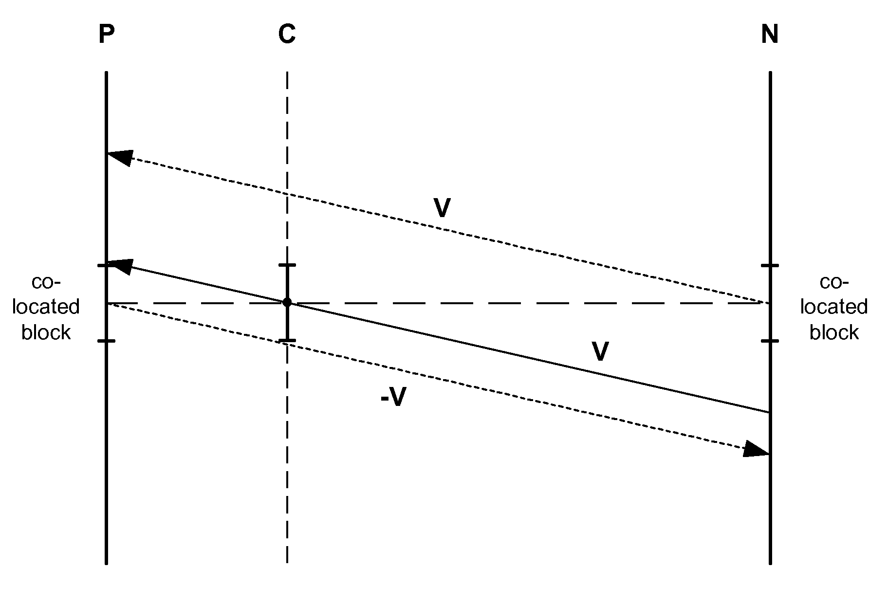
[0019]In addition to the vector V passing through the reference block in C, the same vector but starting from co-located blocks in P and N are tested as well. With co-located blocks are meant blocks in P and N located at the same position as the reference block in the C frame. The error functions are computed for the co-located block in P to position offset −V in N as well as for the co-located block in N to position offset V in P, see FIG. 5. Analysing these results in combination with the original error function, we can, to a large degree, avoid selecting erroneous vectors for the reference blocks in the virtual frame C.

[0020]The additional motion validation will determine if the co-located blocks (one of them or both) will have similar motion, i.e. are part of the same “motion object”, or not. If one or both of the co-located bl...


PUM


Abstract

A method for motion validation in a virtual frame motion estimator includes selecting motion vectors for a virtual frame C, located at a temporal position between a previous frame P and a subsequent frame N, and computation of an extended error function based on the error for a vector V passing from frame P, through a reference block in the virtual frame C, to frame N, and using additional validation measures computed from vectors −V and +V starting from co-located blocks in P and N respectively, thereby reducing the risk for selecting erroneous vectors for said reference blocks in the virtual frame C.

Description

CROSS REFERENCE TO RELATED APPLICATIONS[0001]This application is a Non-provisional Application claiming benefit under 35 USC § 119 (e) to Provisional Application 60 / 744,628 filed on Apr. 11, 2006, the entire contents of which are incorporated herein by reference.BACKGROUND[0002]This disclosure concerns a method for motion validation in a motion estimator used for creating motion compensated interpolated virtual frames of digital images.[0003]In certain applications, such as frame rate conversion, it is necessary to find motion vectors which are temporally offset from the source frames. New frames with temporal locations in-between the source frames are generated through interpolation and motion vectors are needed that define the motion at the temporal location of these new frames. One alternative for getting temporally offset motion vectors is to use a standard motion estimator, such as described in U.S. Pat. No. 5,557,341, to produce motion vectors that describe the motion between ...

Claims


Application Information

Patent Timeline
Patent Type & Authority Applications(United States)
IPC IPC(8): H04N11/02H04B1/66
CPCH04N19/577H04N19/51
Inventor LIDBERG, FREDRIK
Owner DIGITAL VISION
Why Eureka
Try Eureka