Fat depth sensor

a depth sensor and fat technology, applied in the field of methods and methods, can solve the problems of reducing the swept frequency range without sacrificing, requiring more complex and costly equipment capable of generating a wide range of frequencies, and many spurious reflections

Inactive Publication Date: 2006-08-08
CALLAGHAN INNOVATION
View PDF5 Cites 4 Cited by
  • Summary
  • Abstract
  • Description
  • Claims
  • Application Information

AI Technical Summary

Benefits of technology

[0022]Preferably, the processing means is programmed to compute the electrical length (de) of the fat and permittivity (εr) of the tissue by computing the values of electrical length and permittivity that minimise the error function
[0024]Preferably, the processing means is programmed to use at least one iterative regression analysis technique to minimise the error function.
[0036]Preferably, the method further includes the step of computing the electrical length (de) of the fat and permittivity (εr) of the tissue by minimising the error function
[0038]Preferably, the method further includes using at least one iterative regression analysis technique to minimise the error function.

Problems solved by technology

Typical problems associated with the use of microwave energy include the need to focus the energy into a relatively small area or voxel, accounting for the different permittivity between different tissue samples, inaccuracies due to surface variation and the requirement for a robust sensor.
A disadvantage of using wide band signals is the generation of numerous spurious reflections and the requirement to use more complex and costly equipment capable of generating a wide range of frequencies.
Also, the swept frequency range can not be reduced without sacrificing resolution in the detected signals.
Furthermore, the generation and detection of a wide band signal requires relatively expensive equipment in comparison to narrow band systems.
Problems are also encountered when attempting to measure the thickness of fat tissue as it is necessary to resolve the position of the small reflection that arises from the air-fat interface from the much larger and swamping reflection from the fat-meat interface.
The widely used Fast Fourier Transform Technique, when used over a limited bandwidth gives rise to significant errors for relatively minor errors in phase if unknown incidental scatterers are unaccounted for.
However, the computational burden of spectral estimation techniques is relatively expensive, requiring relatively high performance processors and therefore is not well suited to a harsh environment, due to lack of robustness.

Method used


Image

  • Fat depth sensor
  • Fat depth sensor
  • Fat depth sensor

Examples


Embodiment Construction

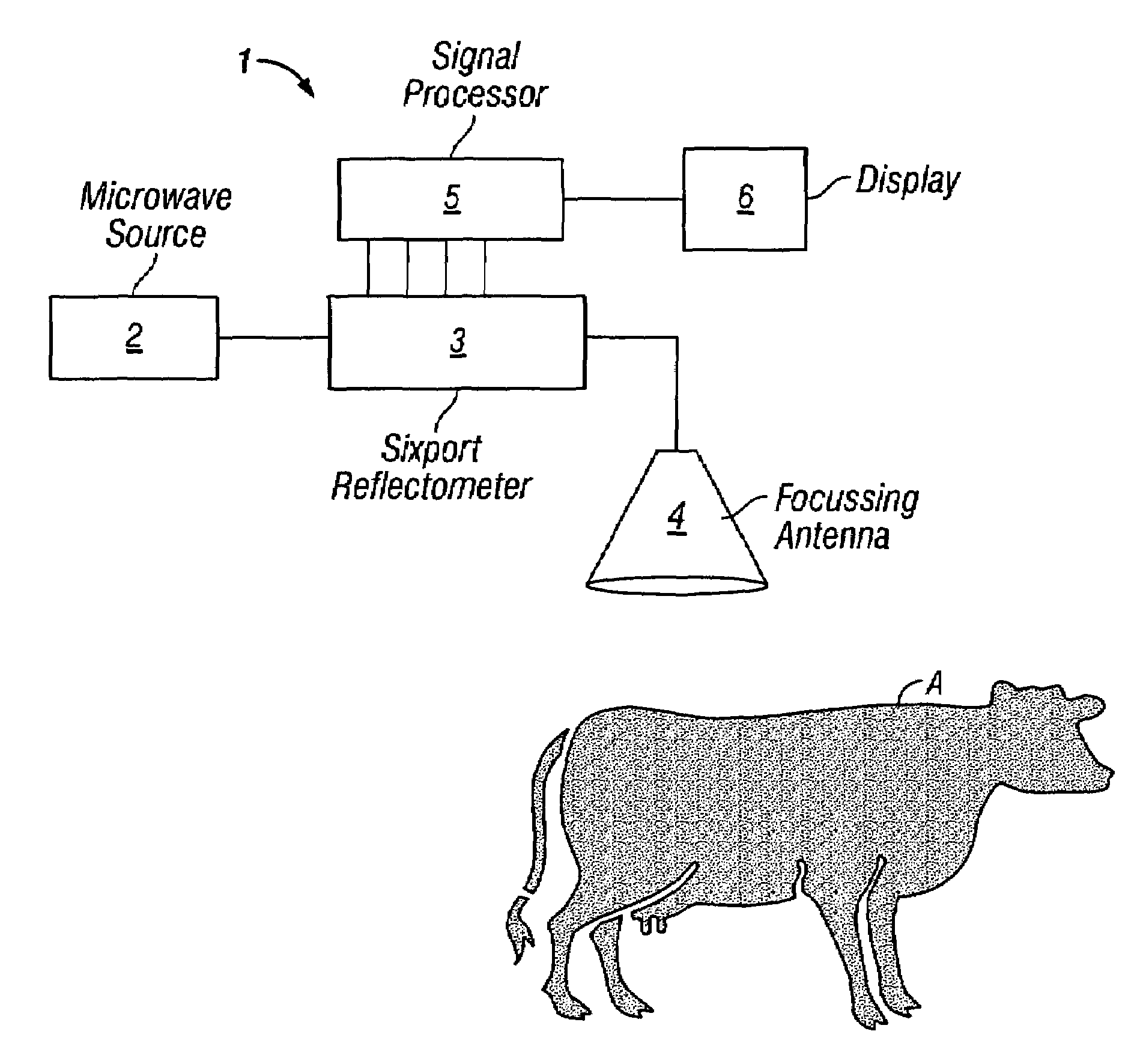
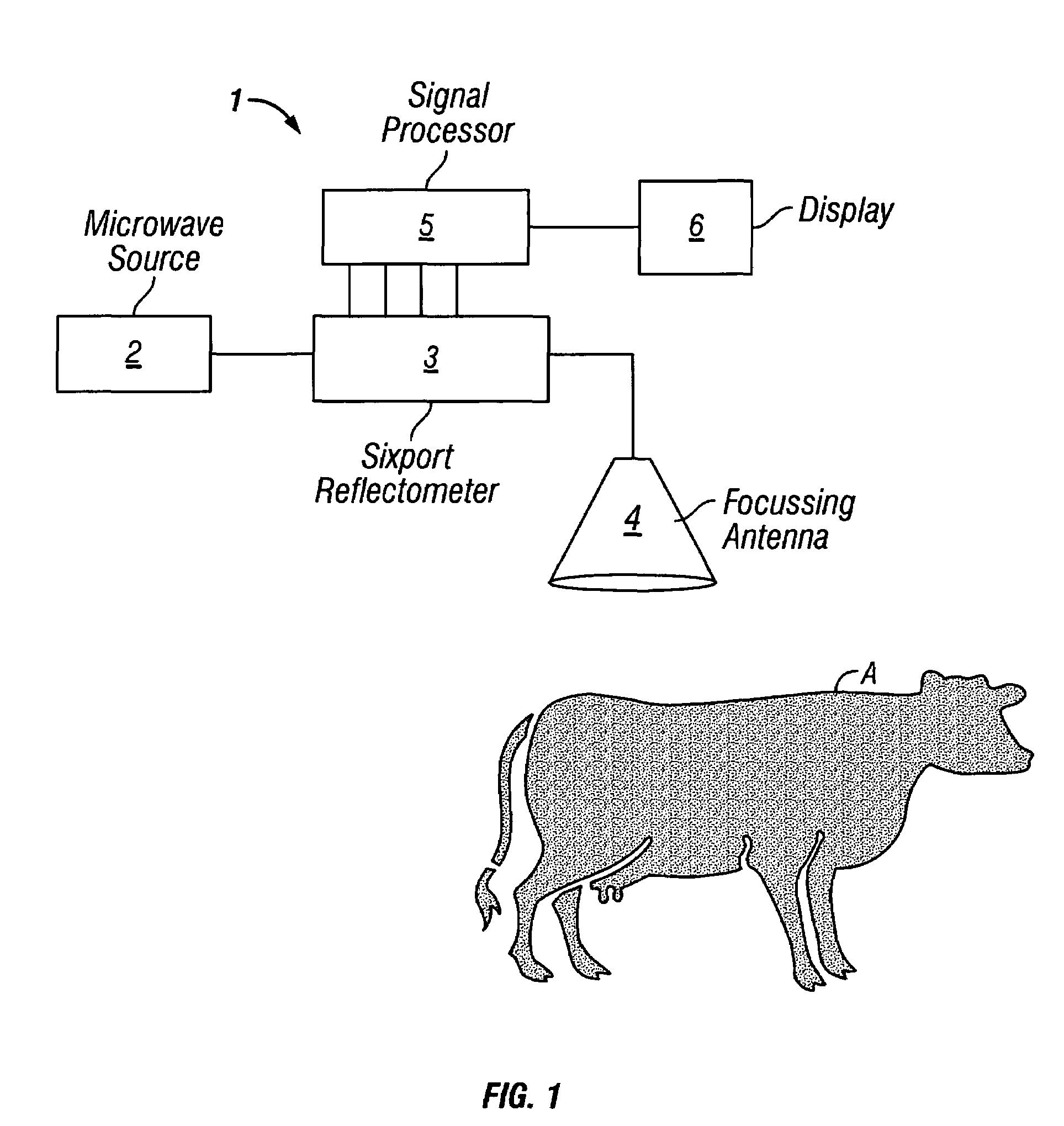
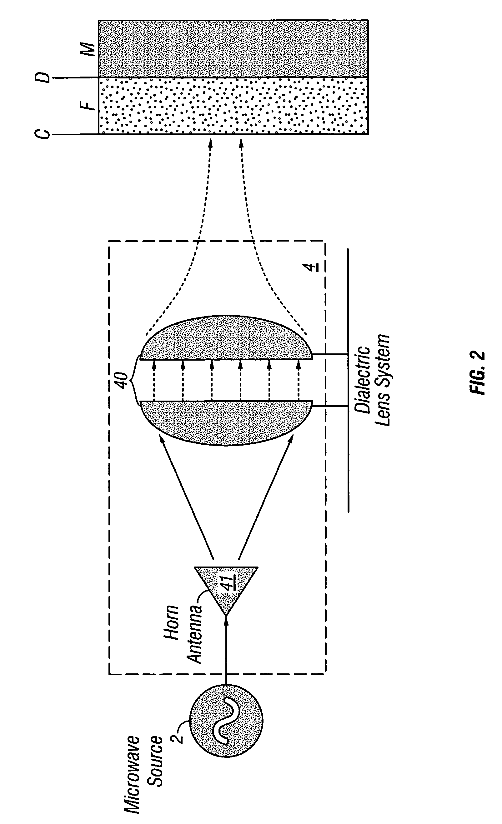
[0045]Referring first to FIG. 1, a block diagram of a sensor 1, according to one aspect of the invention is shown. An animal carcass A, represented in FIG. 1 by a cow, which is to be measured to ascertain the depth of the fat layer F (see FIG. 2) is positioned near the sensor 1.

[0046]The sensor includes a microwave source 2 to generate microwave signals and communicate them to a sixport reflectometer 3 through a waveguide. The sixport reflectometer 3 communicates the microwave signals to a focussing antenna 4, which focuses the microwave signals onto a portion of the animal tissue.

[0047]Traditionally, the microwave source 2 would be used to generate a relatively wideband signal and the reflected energy would be analysed using Fourier Transform techniques. However, to reduce the effects of spurious reflections, provide a high resolution measurement and minimise the computational burden and associated cost and complexity, the present invention uses three discrete narrow-band signals. ...


PUM

PropertyMeasurementUnit
frequencyaaaaaaaaaa
poweraaaaaaaaaa
sizeaaaaaaaaaa

Abstract

A non-invasive sensor suitable for measuring the depth of fat in animal tissue is described, the sensor generating and transmitting focussed discrete narrow band microwave signals into the tissue, receiving reflected microwave signals from the tissue and providing magnitude and phase information of the reflected microwave signals for a processor to compute a value of the fat depth within the tissue.

Description

TECHNICAL FIELD[0001]This application claims the benefit of priority under 35 U.S.C. §120 as a continuation of PCT Application No. PCT / NZ00 / 00249, filed Dec. 13, 2000 (published in English on Jun. 14, 2001 as WO 01 / 42737), which under 35 U.S.C. §119, claims priority to New Zealand Patent Application No. 501765, filed Dec. 13, 1999, both of which are incorporated by reference herein in their entirety.[0002]This invention relates to a method and apparatus for determining the properties of animal tissue and in particular, but not exclusively to a method and apparatus of determining the thickness of a layer of fat on meat.BACKGROUND OF THE INVENTION[0003]The meat industry is becoming increasingly automated with the goal of becoming more efficient. Automated accurate measurement of the properties of animal tissue is therefore important to ensure efficient operation.[0004]In particular, the accurate measurement of the composition and structure of meat carcasses, including fat depth, bone ...

Claims


Application Information

Patent Timeline
Patent Type & Authority Patents(United States)
IPC IPC(8): A61B5/00A22B5/00G01B15/02G01N22/00G01N33/12
CPCG01B15/02G01N33/12G01N22/00Y10S128/92A61B5/0507A61B5/4872A61B2503/40
Inventor HOLMES, WAYNE STEPHEN
Owner CALLAGHAN INNOVATION
Why Eureka
Try Eureka