Screw for composite building materials

a technology for building materials and screws, applied in the direction of screws, threaded fasteners, fastening means, etc., can solve the problems of excessive wear of battery operated screwdrivers, poor suitability of prior art screws for use with new higher density products, and increased risk of bulging problems

Inactive Publication Date: 2007-10-11
YAO SEIBYO
View PDF14 Cites 33 Cited by
  • Summary
  • Abstract
  • Description
  • Claims
  • Application Information

AI Technical Summary

Problems solved by technology

Prior art screws are not well-suited for use with the new higher density products.
This causes excessive wear on battery operated screwdrivers, which are often used to install these molded products.
Finally, the higher density products are more susceptible to the bulging problem described in U.S. Pat. No. 6,000,892.
It is believed that this bulge results from wood chips cut by the lower threads.

Method used


Image

  • Screw for composite building materials
  • Screw for composite building materials
  • Screw for composite building materials

Examples


Embodiment Construction

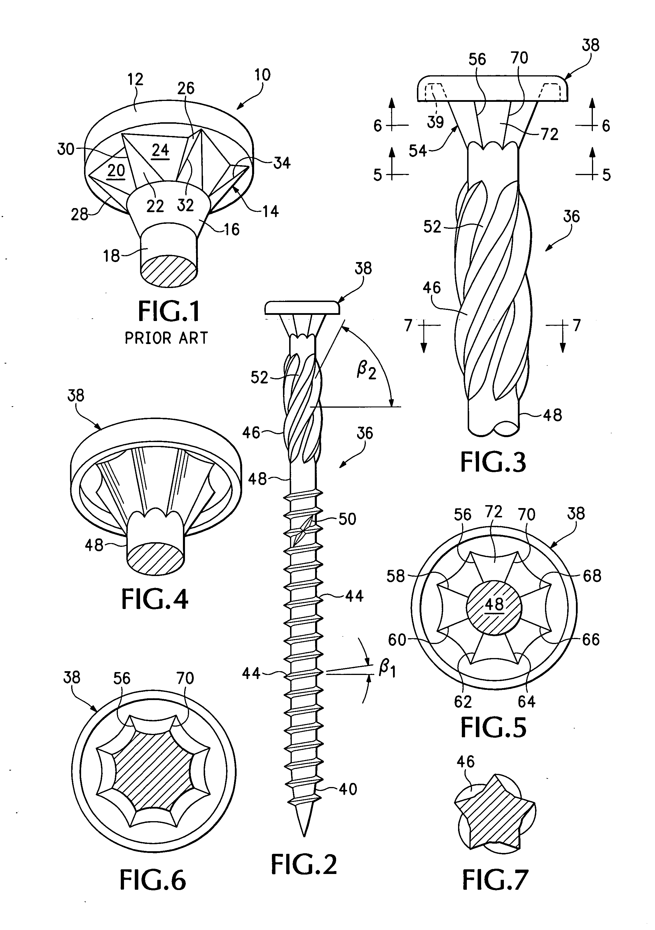
[0019] Turning first to FIG. 1, indicated generally at 10, is the upper portion of the prior art screw. The screw includes a head 12, a self countersinking feature 14, and a transitional frusto-conical portion 16 disposed between countersinking feature 14 and a shaft 18 of the screw.

[0020] Countersinking feature 14 includes a plurality of planar surfaces, like surfaces 20, 22, 24, 26. At the juncture of some of these surfaces, a cutting corner, like corners 28, 30, 32, 34, is formed.

[0021] As the screw of FIG. 1 is driven into a piece of wood, the cutting corners surrounding the screw scrape against the upper surface of the bore and gradually cut a countersunk hole into the upper portion of a bore created by the threads of screw 10 while it drives into its final position. This countersunk hole permits head 12 to be drawn further down into the bore and ideally to the point where the upper surface of head 12 is flush with the surface of the bore.

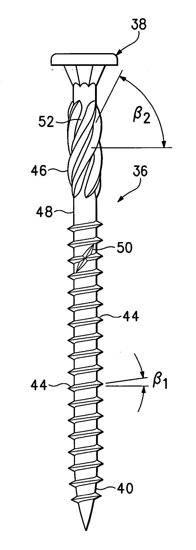
[0022] Turning now to FIG. 2, indica...


PUM

PropertyMeasurementUnit
frusto-conical shapeaaaaaaaaaa
circumferenceaaaaaaaaaa
cross-sectional areaaaaaaaaaaa

Abstract

A screw includes a lower set of cutting threads and an upper set of storage threads, the latter having a larger diameter than the cutting threads. The underside of the head includes an annular groove formed thereabout. A countersink feature is disposed between the underside of the head and the shaft of the screw. It includes a plurality of cutting ribs and a curved surface disposed between each rib pair thereby defining a groove. When the screw is installed in a composite wood-plastic material, cuttings cut by the cutting threads move upwardly and are stored between adjacent storage threads. Material cut by the countersink feature is pushed down the grooves. A space between the countersink feature and the storage threads provides additional room for storing cuttings. As a result, cuttings are retained in the bore thus preventing bulging of the surface around the bore.

Description

BACKGROUND OF THE INVENTION [0001] 1. Field of the Invention [0002] The present invention relates to a screw for use with composite materials such as decking and railing products that are molded from a mixture of plastic and wood. [0003] 2. Description of the Related Art [0004] One such screw is disclosed in U.S. Pat. No. 6,000,892. That screw works well with prior molded products, which include a mixture of approximately 60% of plastic, such as polyvinylchloride, and 40% wood chips. More recently, however, molded materials have much higher proportions of plastic to wood, e.g., 80% plastic and 20% wood. These newer products are much harder and denser than the prior 60% plastic / 40% wood products. Prior art screws are not well-suited for use with the new higher density products. [0005] For example, the new high density products require much higher torque, especially during the latter stages of driving a screw into its final position in which the head is flush with the surface of the p...

Claims


Application Information

Patent Timeline
Patent Type & Authority Applications(United States)
IPC IPC(8): F16B25/10
CPCF16B25/0015F16B25/0047F16B35/065F16B25/10F16B35/041F16B25/0057
Inventor TAKASAKI, SEIICHIROU
Owner YAO SEIBYO
Why Eureka
Try Eureka