
Air conditioning controller

a controller and air conditioning technology, applied in the field of air conditioning controllers, can solve the problems of excessive energy consumption, and achieve the effect of reducing the comfort of occupants, fine seasoning, and largely effective energy saving

Inactive Publication Date: 2007-10-18
KK TOSHIBA
View PDF4 Cites 45 Cited by
  • Summary
  • Abstract
  • Description
  • Claims
  • Application Information

AI Technical Summary

Benefits of technology

[0010]The present invention has been made in order to solve the foregoing problem. An object of the present invention is to provide an air conditioning controller that provides both comfort of occupants and energy saving at the same time by controlling both room temperature and room humidity.
[0012]According to the aspect of the present invention, it is possible to control both of room temperature and room humidity, and thereby to achieve an air conditioning control that is finely seasonable and largely effective in energy saving without decreasing the comfort of occupants.

Problems solved by technology

For the foregoing reason, a conventional dehumidification control has a problem that energy is excessively consumed as compared to a case of a technique for controlling only temperature.

Method used


Image

  • Air conditioning controller
  • Air conditioning controller
  • Air conditioning controller

Examples


first embodiment

[0035]Hereinafter, a description will be provided for an air conditioning controller according to a first embodiment of the present invention by referring to the accompanying drawings. In the following description for the embodiment, PMV is used as a thermal comfort index. Moreover, an air conditioner to be controlled in the embodiment is a system that is capable of separately controlling room temperature and room humidity while saving energy consumption.

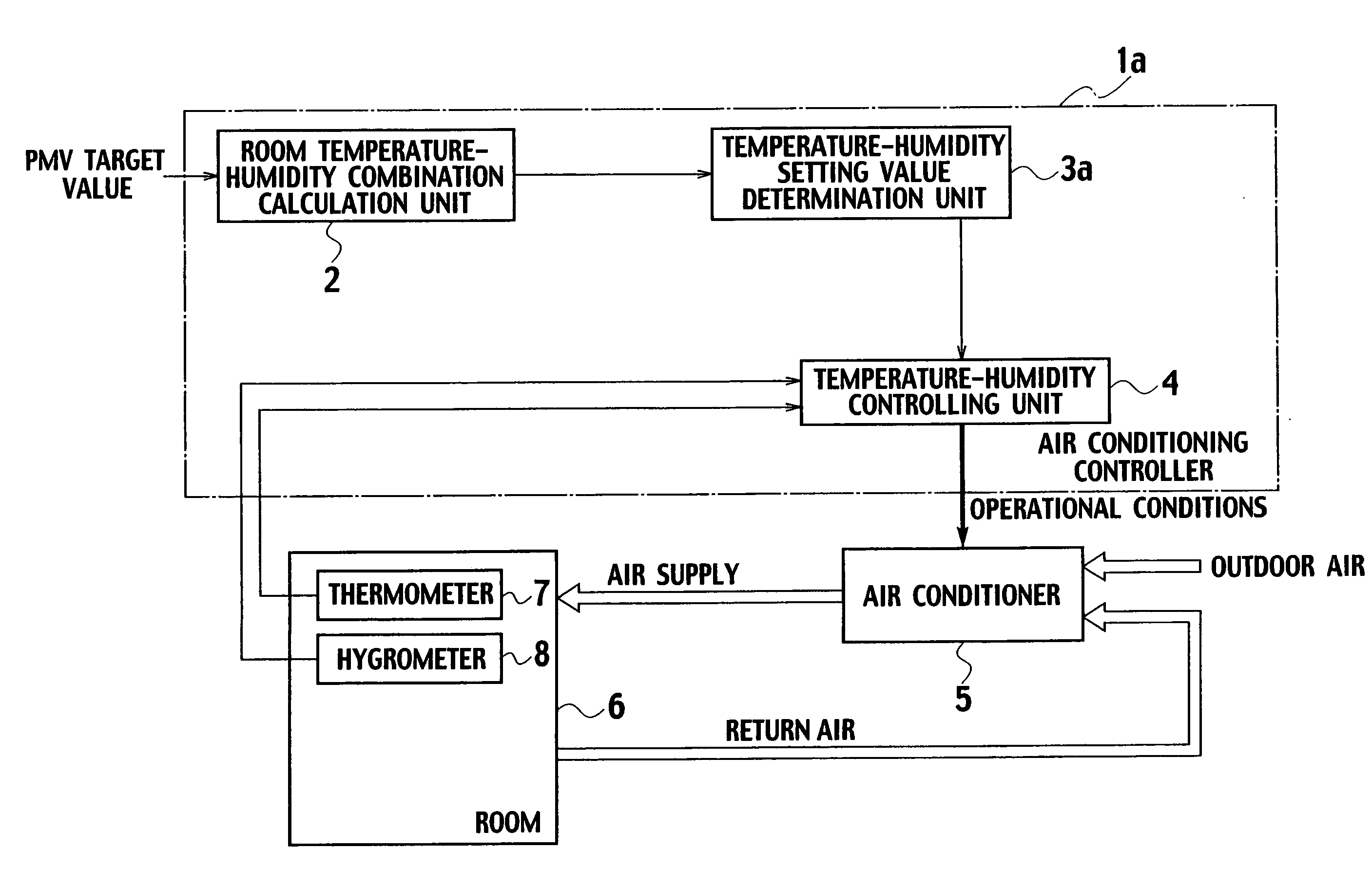
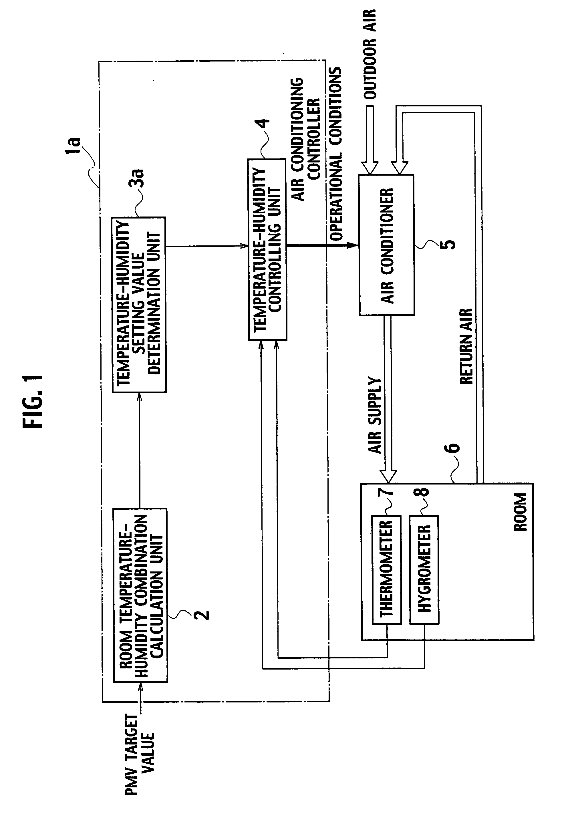
[0036]FIG. 1 is a block diagram showing an air conditioning controller according to the first embodiment of the present invention.

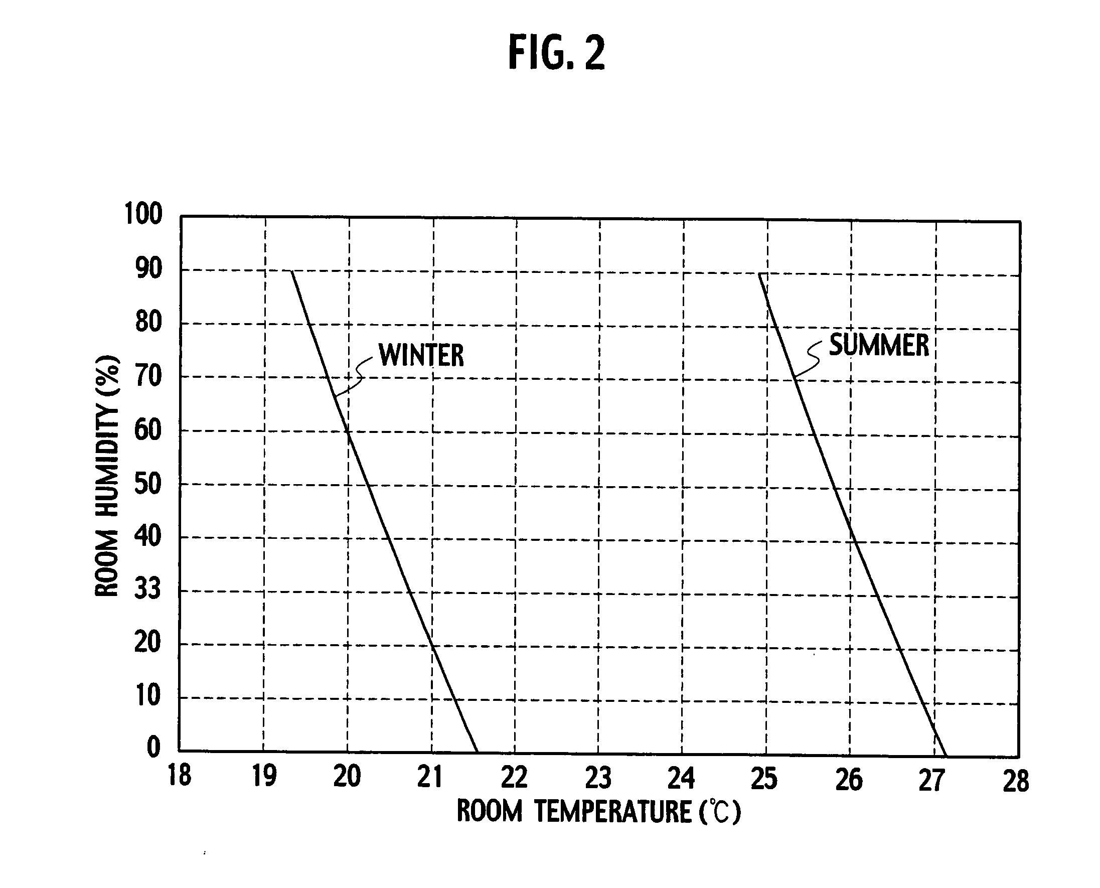
[0037]An air conditioning controller 1a shown in FIG. 1 includes a room temperature-humidity combination calculation unit 2, a temperature-humidity setting value determination unit 3a and a temperature-humidity control unit 4. The room temperature-humidity combination calculation unit 2 calculates combinations of room temperature and room humidity corresponding to each PMV target value. In every fixed cyc...

second embodiment

[0052]FIG. 4 is a block diagram showing an air conditioning controller according to a second embodiment of the present invention. In FIG. 4, the same reference numerals are given to the same components as those in FIG. 1, and the explanation for those components is omitted here.

[0053]An air conditioning controller 1b shown in FIG. 4 includes a room temperature-humidity combination calculation unit 2 for calculating combinations of the room temperature and humidity corresponding to the PMV target value. The air conditioning controller 1b also includes a PMV current value calculation unit 51 for calculating a PMV current value that is a PMV value to be actually targeted at this moment, from a clothing amount setting value and an activity amount setting value. The air conditioning controller 1b further includes a temperature setting value correction unit 52. In a case where the calculated PMV current value is different from the PMV target value, the temperature setting value correction...


PUM


Abstract

An air conditioning controller is provided with a room temperature-humidity combination calculation unit, a temperature-humidity setting value determination unit and a temperature-humidity control unit. The room temperature-humidity combination calculation unit is configured to calculate combinations of room temperature and room humidity corresponding to a target value of a thermal comfort index PMV. The temperature-humidity setting value determination unit is configured to select and determine a combination of the room temperature and humidity that achieves energy saving among the calculated combinations of the room temperature and humidity. The temperature-humidity control unit is configured to separately control the room temperature and humidity so that the room temperature and humidity would measure up respectively to the determined temperature and humidity values.

Description

CROSS-REFERENCE TO RELATED APPLICATION[0001]This application is based upon and claims the benefit of priority from the prior Japanese Application No. 2006-112522, filed on Apr. 14, 2006; the entire contents of which are incorporated herein by reference.BACKGROUND OF THE INVENTION[0002]1. Field of the Invention[0003]The present invention relates to an air conditioning controller achieving an air conditioning control that is finely seasonable and largely effective in energy saving without decreasing comfort in living space.[0004]2. Description of the Related Art[0005]Nowadays, it is said that energy consumption related to air conditioning accounts for approximately half of energy consumption in entire building equipment. For this reason, advancement in energy saving in air conditioning control largely contributes to energy saving in entire building equipment. An office building serving as an amenity space is required to satisfy thermal sensation, that is, so-called comfort of occupant...

Claims


Application Information

Patent Timeline
IPC IPC(8): F24F3/14F25D17/04
CPCF24F11/006F24F11/001F24F11/30F24F2110/00F24F11/62F24F11/74F24F11/46F25B2700/2106F24F2110/20F24F2110/10
Inventor YONEZAWA, KENZOTAKAGI, YASUOIINO, YUTAKANISHIMURA, NOBUTAKA
Owner KK TOSHIBA
Learn More