Hair iron

a technology of hair iron and contact plane, which is applied in the direction of curling irons, curling-tongs, hair equipments, etc., can solve the problem of not being able to easily control the contact pressure over the contact plane, and achieve the effect of facilitating control of the contact pressur

Inactive Publication Date: 2007-10-18
MUKAI TAKASHI
View PDF4 Cites 48 Cited by
  • Summary
  • Abstract
  • Description
  • Claims
  • Application Information

AI Technical Summary

Benefits of technology

[0010] The object of the present invention is to facilitate controlling the contact pressure between reformation plates.

Problems solved by technology

However, the method of using the single spring 227 of the prior art cannot make the contact pressure uniform between the reformation plates 223 and 225 and also cannot easily control the contact pressure over the contact plane for example setting stronger pressure at the top side to the base side relatively or vice versa.

Method used


Image

  • Hair iron
  • Hair iron
  • Hair iron

Examples


Embodiment Construction

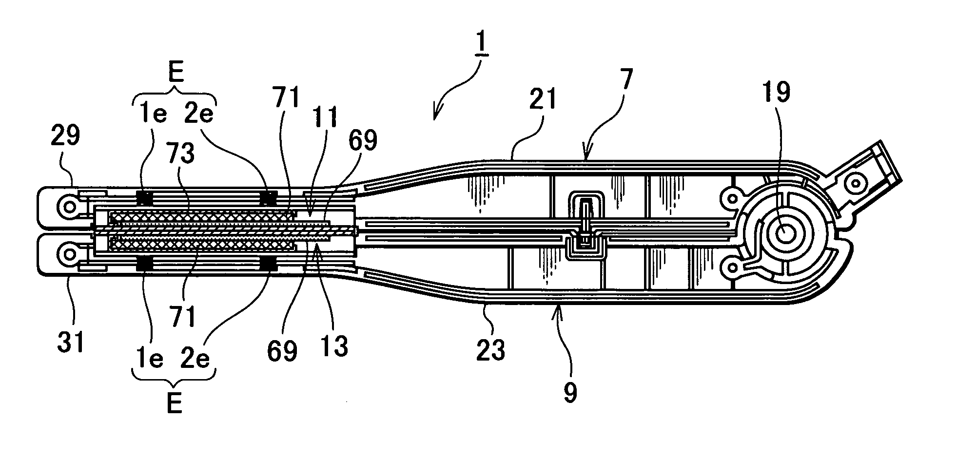
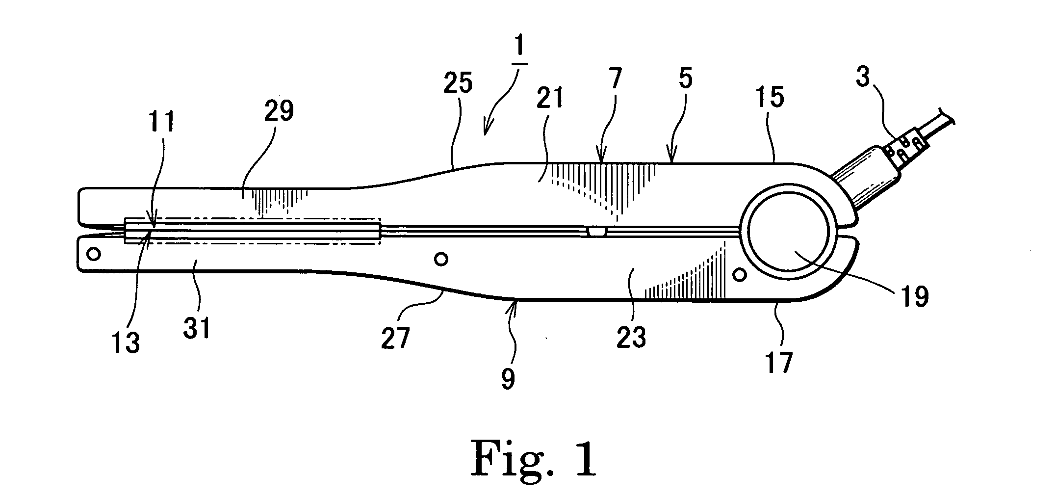
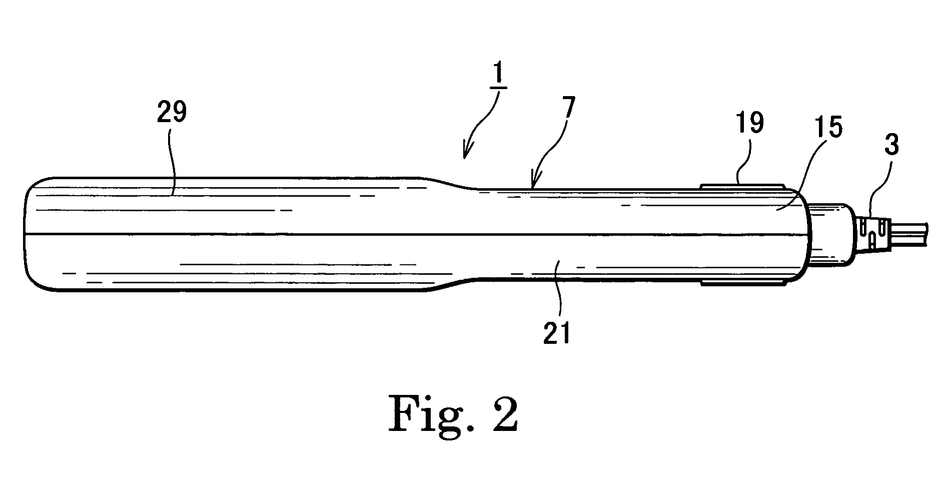
[0028] A hair iron device 1 of an example 1 of the present invention is comprised of two arms 7 and 9. The two arms 7 and 9 including hand holding parts 21 and 23 are articulated at their base end 15 and 17 to make the top side corresponding to the other end of the arms 7 and 9 moving to closed position. The two arms 7 and 9 operate holding action of the top side by grasping the hand holding part 21 and 23. The arms 7 and 9 have a pair of reformation plates 11 and 13. The pair of reformation plates 11 and 13 is placed at the top part 29 and 31 of the two arms 7 and 9 to face each other. The reformation plates 11 and 13 each includes heated thermal plate portion 67. The heated thermal plate portion 67 has a reformation plane 87 serving as a surface of the reformation plate. The reformation planes 87 of the reformation plates 11 and 13 are contacted with each other at the closed position. The heated thermal plate portion 67 of the reformation plates 11 and 13 holds hair at the reforma...


PUM


Abstract

A hair iron comprises of a pair of holding arms pivotally articulated at one end, operating holding action by grasping the hand hold part placed in the center of the holding arms. A pair of reformation plates is placed on the top side of the two arms with their reformation plane facing each other for straightening hair by holding hair in between the reformation plates with heat added by the heat plate. The reformation plates are movably held on the holding arms with a plurality of coil springs. The plurality of coil springs also pushes the reformation plates each other to their facing direction to control the state of holding hair. Thus the control of the contact pressure and also the control of the uniformity of the contact pressure over the reformation plane 87 can be facilitated.

Description

BACKGROUND OF THE INVENTION [0001] 1. Field of the Invention [0002] The present invention relates to a hair iron device for reforming hair. [0003] 2. Description of Related Art [0004] An example of a hair iron device shown in FIGS. 9A and 9B is disclosed in Japanese Unexamined Patent Application Publication No. 2001-137038. FIG. 9A is an entire view of the hair iron. FIG. 9B is a cross-sectional view of the hair iron. [0005] As shown in FIGS. 9A and 9B, the hair iron 201 has a main body 203 and a power supply code 205 connected to the main body 203. A thermal controller 207 is placed in the midway of the power supply code 205. A power plug 209 is connected to an end of the power supply code 205. [0006] The main body 203 of the hair iron 201 comprises a pair of arms 211 and 213 made of resin for holding hair. These two arms 211 and 213 are pivotally articulated at one end of the arms 215 and 217. A pair of reformation plates 223 and 225 is movably held on the arms facing each other. ...

Claims


Application Information

Patent Timeline
Patent Type & Authority Applications(United States)
IPC IPC(8): A45D1/00
CPCA45D1/04A45D2001/004A45D1/06
Inventor MUKAI, TAKASHI
Owner MUKAI TAKASHI
Why Eureka
Try Eureka