Automatically deployable and retractable rear ladder, particularly for emergency vehicles

a rear ladder, automatic technology, applied in ladders, construction, building construction, etc., can solve the problems of reducing the likelihood of someone traversing the ladder, and achieve the effect of reducing the risk of injury, minimizing the open space needed, and saving tim

Inactive Publication Date: 2007-10-18
VT SPECIALIZED VEHICLES
View PDF14 Cites 34 Cited by
  • Summary
  • Abstract
  • Description
  • Claims
  • Application Information

AI Technical Summary

Benefits of technology

[0007] The present invention is directed to a two-rail rear-angled ladder that is automatically deployable and retractable with minimal or no human intervention, thereby saving time and / or creating less risk for injury. The ladder is deployed from the rear of a vehicle. Only a partial portion of the ladder's length is required to be deployed before the ladder will tilt downward towards the ground. This minimizes open space needed behind the vehicle to deploy the ladder and reduces safety hazards caused as a result of deploying or retracting a full length ladder.
[0009] Thereafter, a second or ladder motor drive unit attached to the ladder rail deploys the ladder along a second ladder rail system toward the ground at the titled angle away from the vehicle. In this manner, open space required for deployment of the ladder is minimized to prevent accidents caused by deploying and retracting the ladder. Further, by employing the two drive system, the carriage does not have to tilt or pivot to fully deploy the ladder.
[0010] The ladder also contains a bottom section that is hingedly attached to a top section of the ladder. In this manner, the bottom section of the ladder can be flipped onto the top section of the ladder to minimize storage space when using a ladder that may otherwise be too long for the vehicle roof. Further, this allows the top section of the ladder to be fully deployed without the top section touching the ground during the automatic deployment process so that persons do not traverse the latter where the ladder ground contact is unknowingly believed to be stable. After full deployment, the bottom section can be flipped open to engage the ladder with ground in a controlled manner. This decreases the likelihood someone will traverse the ladder without the ladder being coupled to the ground in a stable manner.
[0011] In a second ladder embodiment, two carriage screw shafts rather than one carriage screw shaft are provided to move the carriage along the roof rail. The two carriage screw shafts are provided on each side of a center axis through the carriage drive. In this manner, the carriage screw shafts are moved out of the walking area of the roof of the vehicle. The carriage drive unit drives both the carriage screw shafts at the same time in unison to move the carriage along the roof to deploy and retract the ladder. Providing two carriage screw shafts allows the carriage drive unit to move the carriage and thus the ladder more slowly for greater control during deployment and retraction.

Problems solved by technology

This decreases the likelihood someone will traverse the ladder without the ladder being coupled to the ground in a stable manner.

Method used


Image

  • Automatically deployable and retractable rear ladder, particularly for emergency vehicles
  • Automatically deployable and retractable rear ladder, particularly for emergency vehicles
  • Automatically deployable and retractable rear ladder, particularly for emergency vehicles

Examples


Embodiment Construction

[0042] The embodiments set forth below represent the necessary information to enable those skilled in the art to practice the invention and illustrate the best mode of practicing the invention. Upon reading the following description in light of the accompanying drawing figures, those skilled in the art will understand the concepts of the invention and will recognize applications of these concepts not particularly addressed herein. It should be understood that these concepts and applications fall within the scope of the disclosure and the accompanying claims.

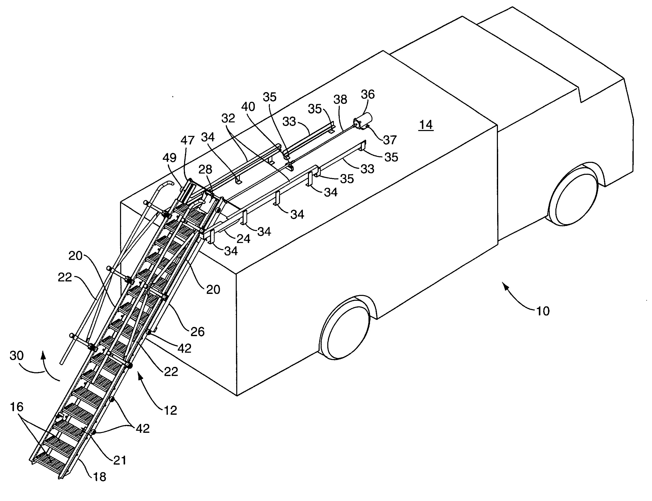
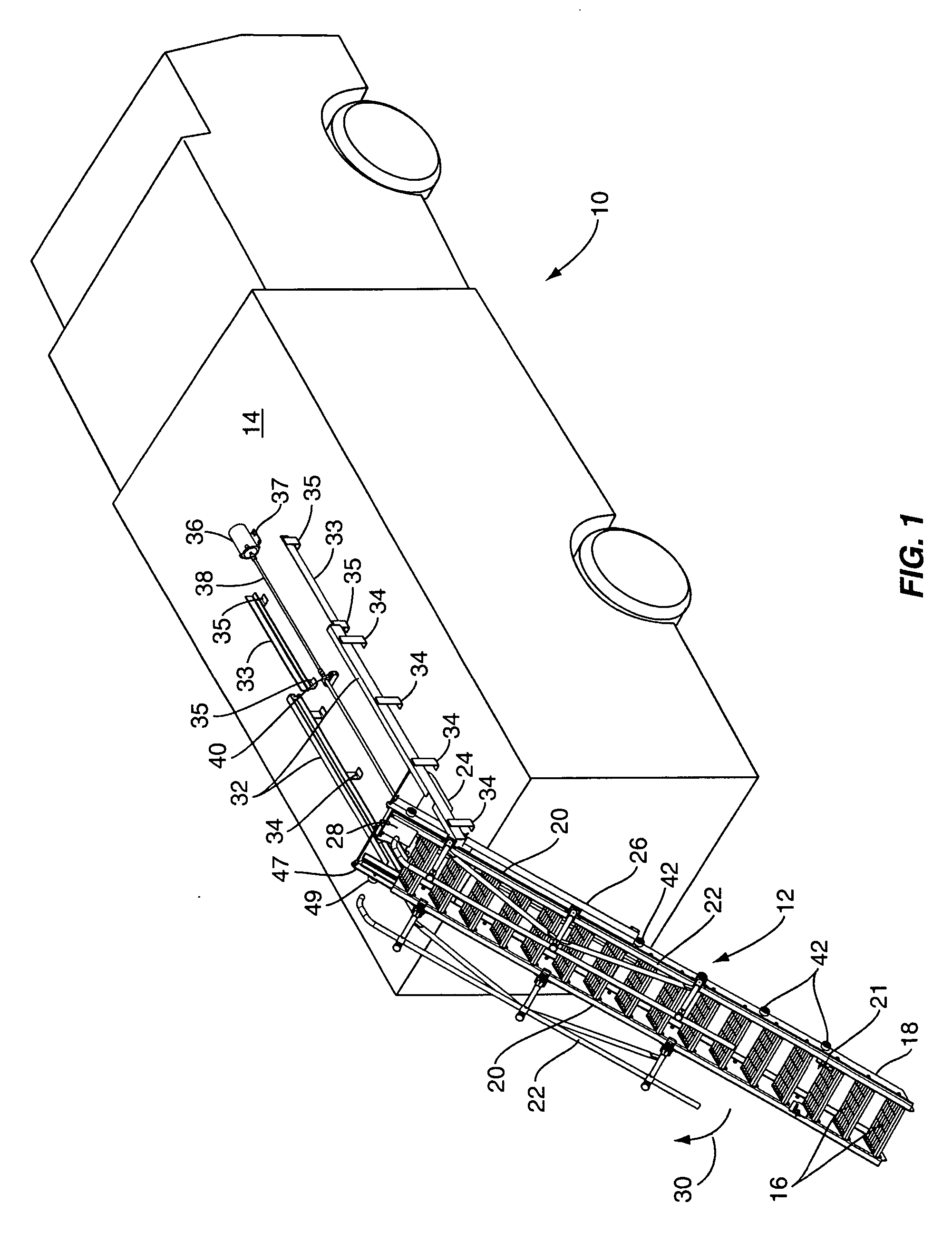
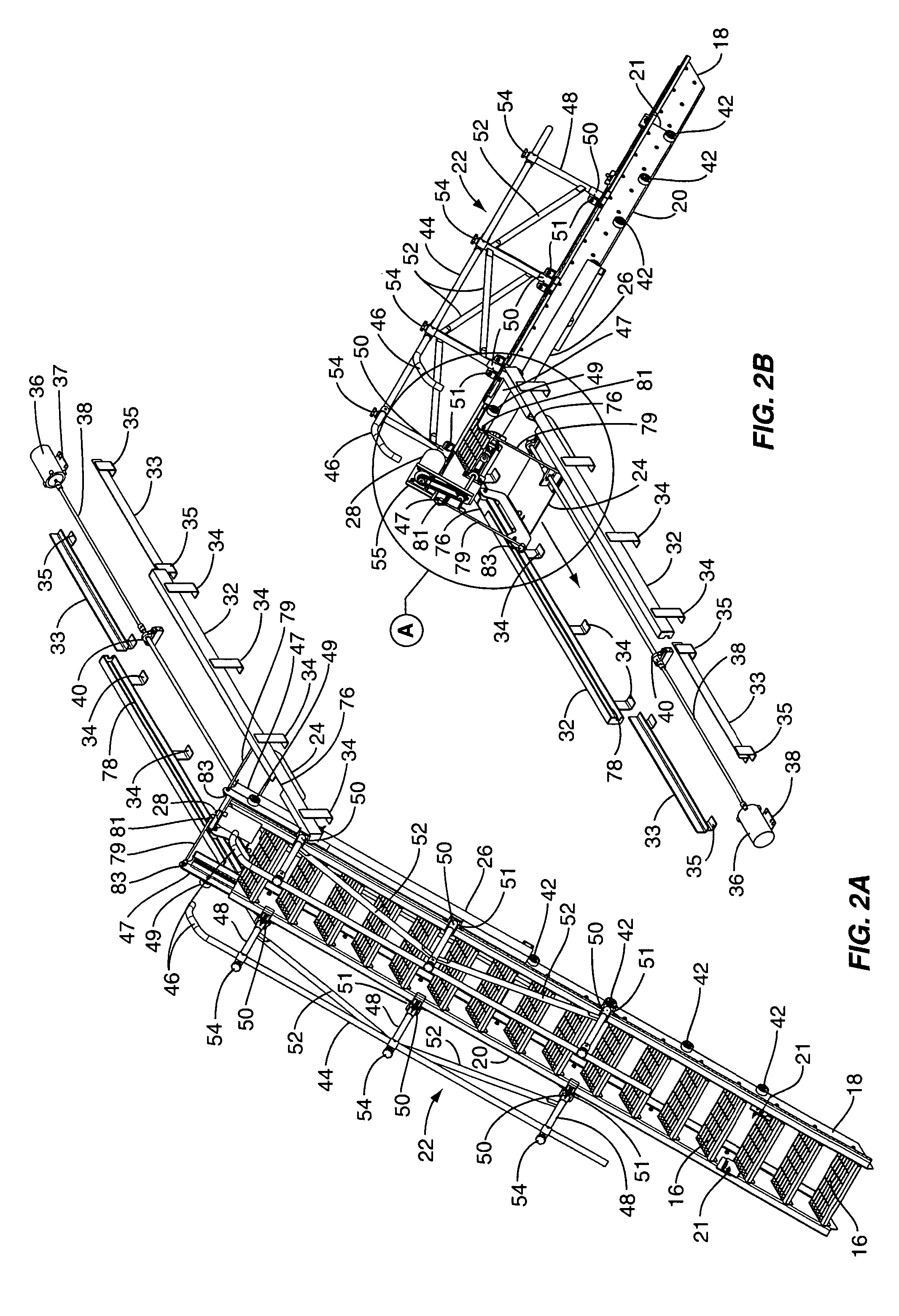
[0043] The drawings of the application illustrate the ladder in its fully deployed position through a retraction process until fully stored on the roof of the vehicle. Thus, deployment of the ladder occurs in reverse and thus the discussion below also inherently discloses the deployment process. An overview of the ladder and the components that allow for its deployment and retraction will be described generally in the descriptio...


PUM


Abstract

A two-rail rear ladder system that automatically deploys and retracts a ladder from a vehicle, such as an emergency vehicle. The ladder is deployable and retractable with minimal or no human intervention, thereby saving time and / or creating less risk for injury. The ladder is deployed from the rear of a vehicle and rests at an angle on the ground when fully deployed. A two-stage drive unit system is used to deploy and retract the ladder. One drive unit deploys and retracts the ladder on a first rail to a position where the ladder tilts towards the ground. The second drive unit deploys and retracts the ladder from the tilted position to and from the ground on a second rail. Only a partial portion of the ladder's length is required to be deployed before the ladder will tilt downward towards the ground thereby minimizing open space needed behind the vehicle to deploy the ladder.

Description

FIELD OF THE INVENTION [0001] The present invention relates to an automatically deployable and retractable ladder device, system, and method for use on vehicles, particularly emergency vehicles. BACKGROUND OF THE INVENTION [0002] It is common to provide a ladder at the rear of a truck or vehicle, and in particular an emergency related vehicle, for access to the roof. Storage compartments and other necessary items may be stored on top of the vehicle. This type of ladder is commonly referred to as a rear ladder. Most rear ladders are fixedly attached in a vertical arrangement to the rear of the vehicle. The ladder is typically comprised of handrails that are attached and run substantially parallel to the rear of the vehicle with perpendicular steps therebetween. Persons desiring to access the roof of the vehicle scale the ladder until they reach the roof of the vehicle. [0003] Because these fixedly mounted rear ladders are parallel to the rear of the vehicle, it is more difficult to s...

Claims


Application Information

Patent Timeline
Patent Type & Authority Applications(United States)
IPC IPC(8): E06C5/00
CPCE06C7/081E06C5/04
Inventor BROOKSHIRE, CURTIS B. JR.LAFAUCI, DOUGLAS M.ECKMAN, GARY L.
Owner VT SPECIALIZED VEHICLES
Why Eureka
Try Eureka