Push-Action Slide Case

Inactive Publication Date: 2007-10-25
YOSHIDA KOGYO KK
View PDF27 Cites 5 Cited by
  • Summary
  • Abstract
  • Description
  • Claims
  • Application Information

AI Technical Summary

Benefits of technology

[0004] The present invention has been contrived in consideration of the above-mentioned circumstance. It is an object of the present invention to provide a push-action slide case having excellent productivity and capable of assuring reliable push-into / eject-out operation of a storage body even for long term use. Solution

Problems solved by technology

In the above-mentioned related art, there is a problem with its productivity where, in combining the storage tray and the main case body by inserting the storage tray through the opening into the main case body, the swing arm can not be easily guided into the curved guide ditch due to its swing movement.
In addition, another problem is pointed out.
That is, because the push-into / eject-out operation of the storage tray is repeated many times, the swing arm is easily worn out due to its swing movement repeated along with such operations, resulting in deteriorated engagement function of the swing arm being guided into the curved guide ditch and the pair of engagement means being engaged.
Therefore, the functionality of keeping the storage tray contained within the main case body may be lost early, and with this disadvantage, the slide case becomes unsuitable for long term use.

Method used


Image

  • Push-Action Slide Case
  • Push-Action Slide Case
  • Push-Action Slide Case

Examples


Embodiment Construction

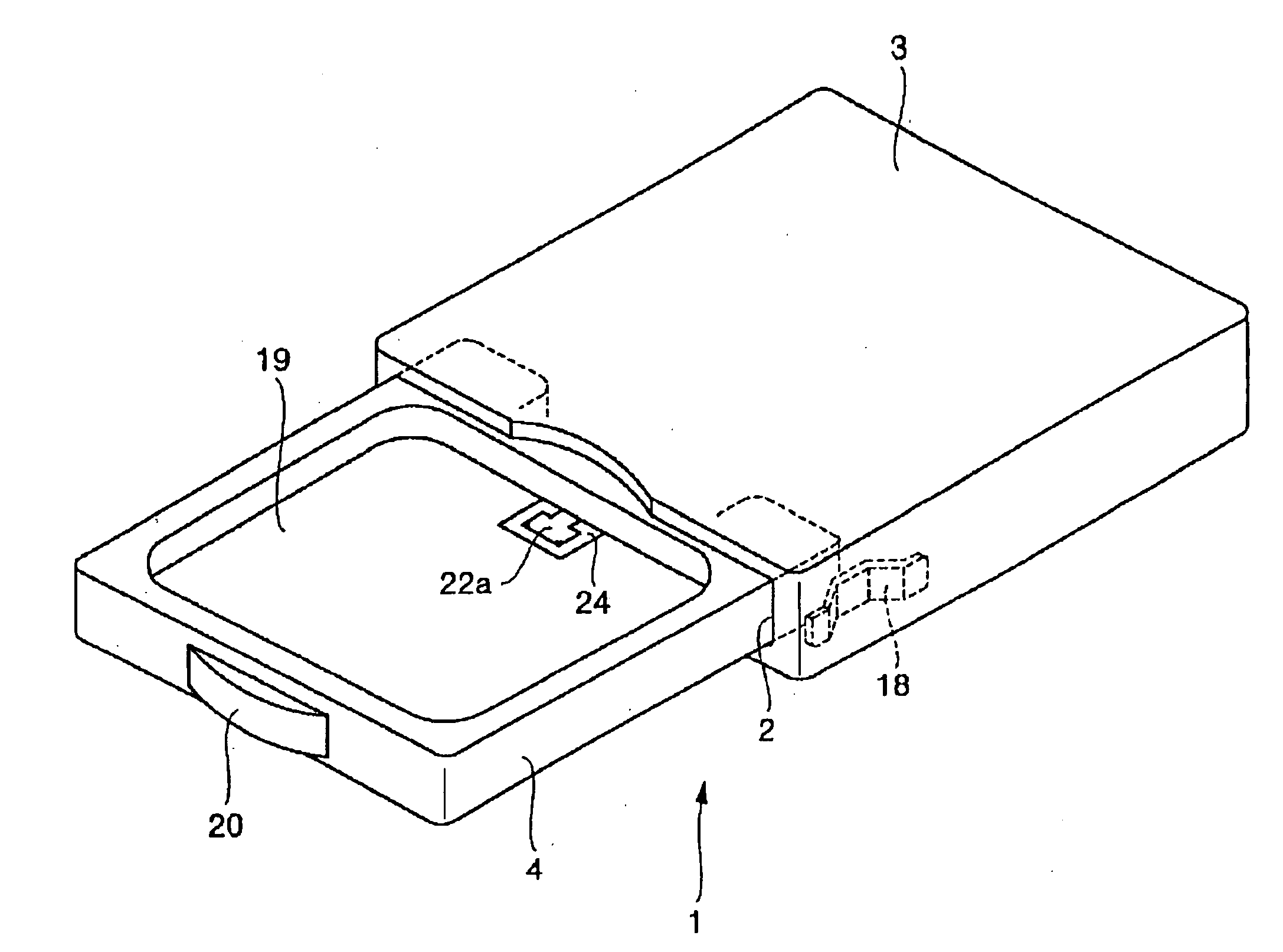
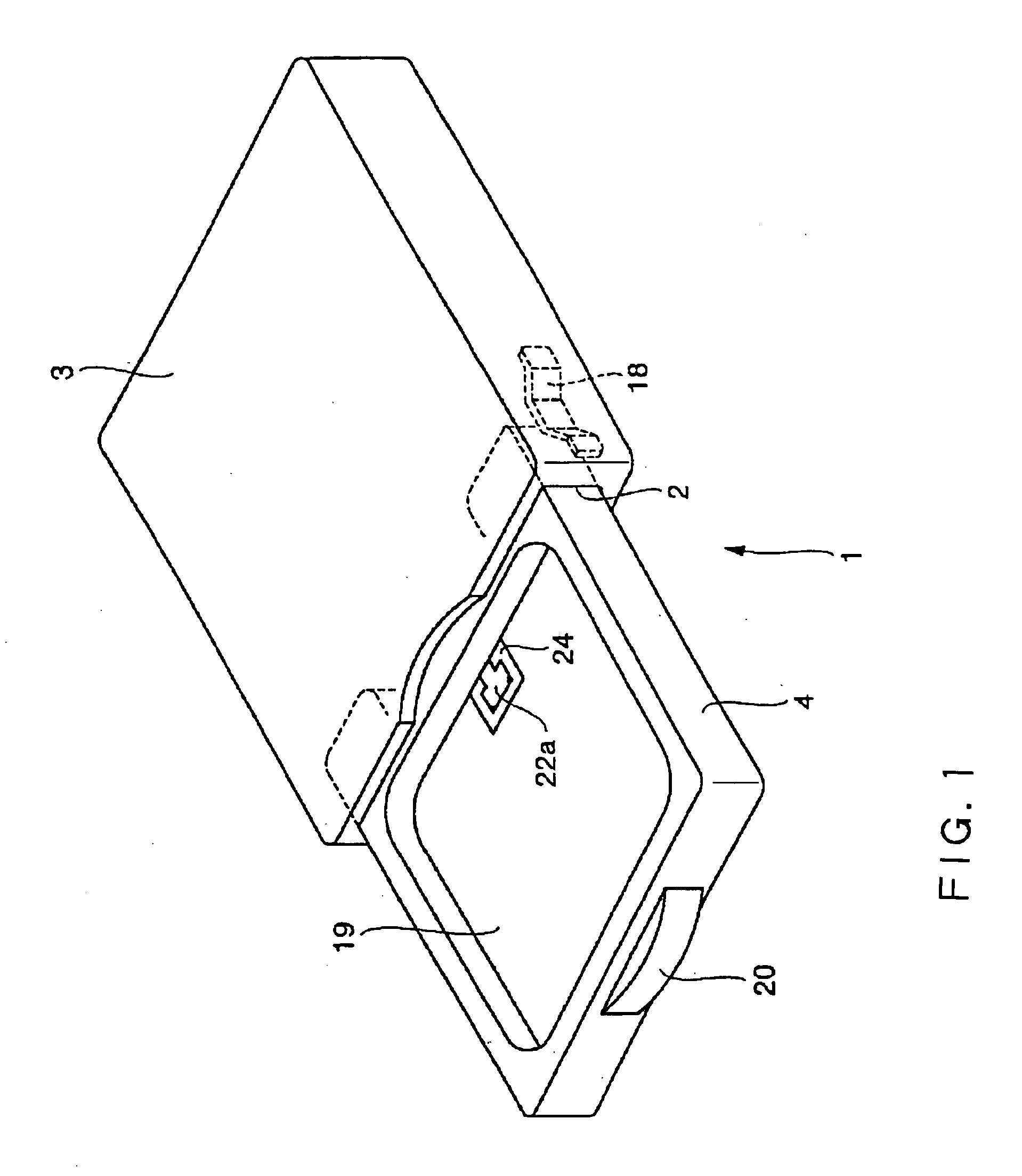
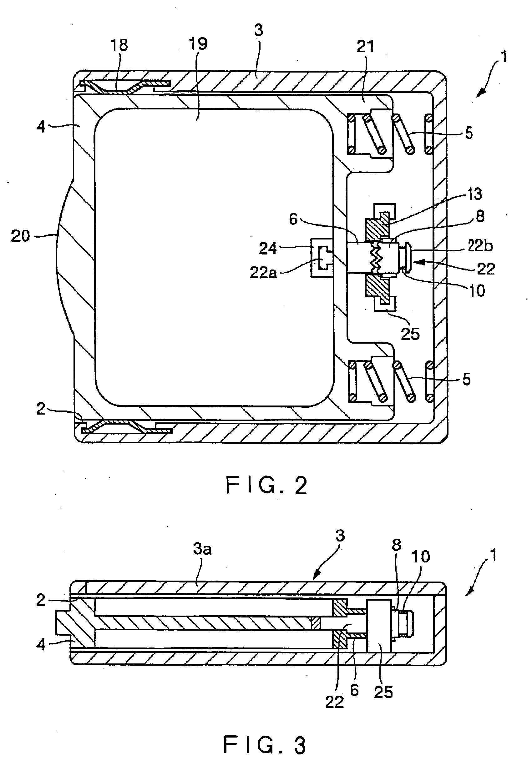
[0030] In the following, a preferred embodiment of a push-action slide case according to the present invention is described in detail with reference to the accompanying drawings. As shown in FIGS. 1 to 6, a push-action slide case 1 of the present embodiment basically comprises a hollow main case body 3 having an opening 2 on its one side, a storage body 4 slidably placed in the main case body 3 and adapted to be pushed into the inside of the main case body 3 through the opening 2 toward the other side of the main case body 3, first springs 5 as first urging members to constantly push the storage body 4 for it to be ejected from the main case body 3, a cylindrical positioner 6 which is integrally formed on the storage body 4 in a shape protruding in the direction of the push-into operation of the storage body 4, positioning ditches 7 which are formed along the periphery of the positioner 6, a cylindrical rotator 8 which is disposed so as to abut against the positioner 6 along the dir...


PUM


Abstract

[Object] To provide a push-action slide case having excellent productivity and capable of assuring reliable push-into / eject-out operation of a storage body even for long term use. [Solution] For assembling a storage body 4, first, a second spring 10 is made abut against a rotator 8 which is already engaged with a positioner 6, then a shaft 22 is inserted into the storage body 4 from the side of the second spring 10, and a latch projection 22a of the shaft 22 is fixed to the storage body 4 by a holding piece 24. In addition, first springs 5 are attached in cylindrical parts 21. On the other hand, for a main case body 3, a ceiling part 3a as a separate body is first removed from the main case body 3, then a holding block 13 is fixed into a holding piece 25 at the bottom of the main case body 3, and elastic pieces 18 are attached to their appropriate positions. Then, the ceiling part 3a is put back on the main case body 3 to form a box body shape. After completing assembling each of the storage body 4 and the main case body 3 in this way, the storage body 4 is inserted into the main case body 3 through an opening 2 to finish the assembly of the slide case as a whole.

Description

FIELD OF THE INVENTION [0001] The present invention relates to a push-action slide case having excellent productivity and capable of assuring reliable push-into / eject-out operation of a storage body even for long term use. BACKGROUND ART [0002] As a slide case which consists of a combination of a main case body and a storage body adapted to be taken into / out of the main case body through an opening of the same, there is known an example disclosed in Japanese Utility Model Publication of Examined Application No. 7-25297. In this document, a slide-in / out type case mainly comprises a main case body having an opening on its one side, and a storage tray adapted to be slidably taken out of the main case body through the opening and to be pushed into the opening to be contained within the main case body. In this slide case, an urging means for constantly pushing the storage tray outward is provided between the main case body and the storage tray, and a swing arm having an engagement means ...

Claims


Application Information

Patent Timeline
IPC IPC(8): A47B88/00G11B33/04B65D6/06
CPCG11B33/0416B65D11/12E05C19/022
Inventor YUHARA, YUKITOMOTOKUSHITA, TAKAYUKI
Owner YOSHIDA KOGYO KK
Why Eureka
Try Eureka