Opposed functional coatings having comparable single surface reflectances

a technology of single surface reflectance and functional coatings, applied in the field of thin film coatings, can solve the problems of high reflective coatings, less reflective thin film titanium dioxide coatings, and undesirable appearance,

Active Publication Date: 2007-10-25
CARDINAL CG
View PDF99 Cites 64 Cited by
  • Summary
  • Abstract
  • Description
  • Claims
  • Application Information

AI Technical Summary

Benefits of technology

The patent describes a method for depositing a low-maintenance coating and a low-emissivity coating onto a window pane. The low-maintenance coating has a single surface reflectance that is less than three times the low-emissivity coating. The low-maintenance coating can include a titanium-containing film and a silicon-containing base film. The method can be carried out while maintaining the pane at a temperature of less than about 250 degrees Celsius. The technical effect of this patent is to provide a window pane with improved low-maintenance and low-emissivity coatings that help to reduce energy consumption and provide better insulation.

Problems solved by technology

Technical Problem: This patent describes how it's possible to make a glass panel that has all these great features - being easy to maintain, insulating from temperature changes, having clear visibility, and giving off minimal glare.

Method used


Image

  • Opposed functional coatings having comparable single surface reflectances
  • Opposed functional coatings having comparable single surface reflectances
  • Opposed functional coatings having comparable single surface reflectances

Examples


example

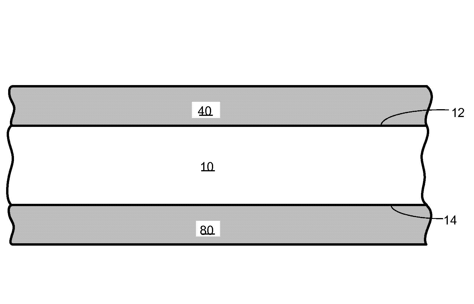
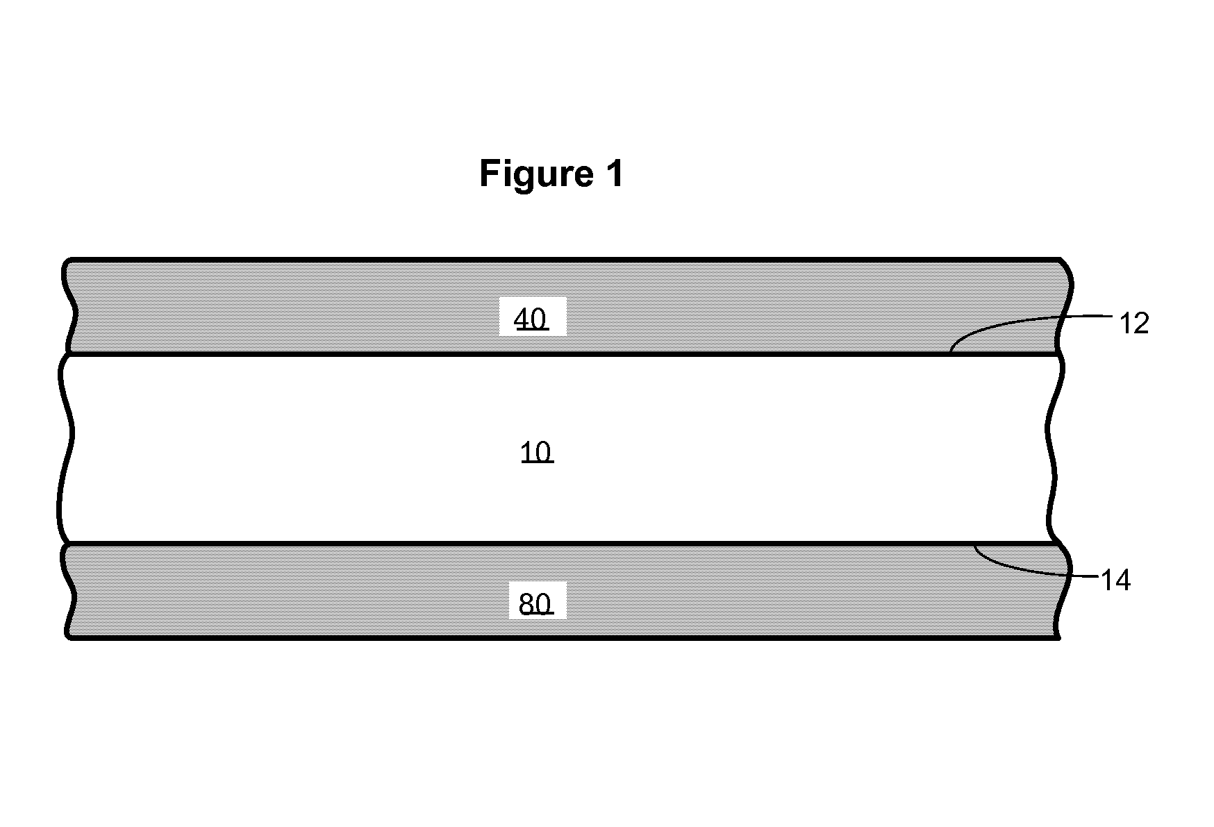
[0051]Reflectance measurements were obtained for certain exemplary low-emissivity and low-maintenance coatings. Four glass substrates were obtained, each being coating-free on one major surface and having a low-maintenance coating on the opposite major surface. The low-maintenance coating on each substrate was a coating as depicted in Table 1 above. Four additional glass substrates were obtained, each being coating-free on one major surface and having a low-emissivity coating on the opposite major surface. The low-emissivity coating on each of these four substrates was a coating as depicted in Table 2.

[0052]The coating-free surface of each glass substrate was chemically etched in order to remove substantially all materials that contribute to reflection. Armour Etch glass etching cream was applied to the coating-free surface with a sponge paint brush. Each substrate was placed inside a fume hood for approximately 30 minutes to etch. The etching cream was then removed by washing with ...


PUM

PropertyMeasurementUnit
Temperatureaaaaaaaaaa
Percent by massaaaaaaaaaa
Weightaaaaaaaaaa

Abstract

A sheet-like pane bearing a low-maintenance coating on one surface and a low-emissivity coating on the opposite surface, wherein one of the low-maintenance coating and the low-emissivity coating has a single surface reflectivity of less than 3 times, and more than one-third, that of the other coating.

Description


Claims


Application Information

Patent Timeline
Owner CARDINAL CG
Why Eureka
Try Eureka