Low-emissivity coating having low solar reflectance

a low-emissivity, solar reflectance technology, applied in the field of coatings, can solve the problems of reflected radiation becoming problematic, more significant, and also more significant, and achieve the effect of reducing the number of reflected radiation

Inactive Publication Date: 2006-06-20
CARDINAL CG
View PDF163 Cites 131 Cited by
  • Summary
  • Abstract
  • Description
  • Claims
  • Application Information

AI Technical Summary

Benefits of technology

[0009]In certain embodiments, the invention provides a pane bearing a low-emissivity coating. In these embodiments, the low-emissivity coating comprises an infrared-reflective layer, a high absorption primary layer, and a middle coat. This infrared-reflective layer comprises material that is highly reflective of infrared radiation. The high absorption primary layer comprises material that is highly absorptive of solar radiation. The high absorption primary layer includes at least about 100 angstroms of film (e.g., has a thickness of at least about 100 angstroms). The middle coat comprises at least one transparent dielectric film and is positioned between the high absorption primary layer and the infrared-reflective layer.
[0010]In certain embodiments, the invention provides a pane bearing a low-emissivity coating. In the present embodiments, the coating comprising the following sequence of films (which are not necessarily contiguous to one another): an inner coat comprising at least one transparent dielectric film; a high absorption primary layer comprising material that is highly absorptive of solar radiation, the high absorption primary layer including at least about 100 angstroms of film (e.g., having a thickness of at least about 100 angstroms); a middle coat comprising at least one transparent dielectric film; an infrared-reflective layer comprising material that is highly reflective of infrared radiation; a high absorption blocker layer comprising material that is highly absorptive of solar radiation, the high absorption blocker layer including at least about 75 angstroms of film (e.g., having a thickness of at least about 75 angstroms); and an outer coat comprising at least one transparent dielectric film.
[0011]In certain embodiments, the invention provides a method of producing coated substrates. The method comprises providing a pane having generally-opposed first and second major surfaces. A low-emissivity coating is deposited upon one of the major surfaces of the pane. This low-emissivity coating comprises an infrared-reflective layer, a high absorption primary layer, and a middle coat. The infrared-reflective layer comprises material that is highly reflective of infrared radiation. The high absorption primary layer comprises material that is highly absorptive of solar radiation. The high absorption primary layer includes at least about 100 angstroms of film (e.g., has a thickness of at least about 100 angstroms). The middle coat comprises at least one transparent dielectric film and is positioned between the high absorption primary layer and the infrared-reflective layer. In some cases, the method comprises depositing the infrared-reflective layer as a silver-containing film. The method optionally comprises depositing the infrared-reflective layer at a thickness of at least about 50 angstroms. In some cases, the method comprises depositing the high absorption primary layer as a titanium-containing film. For example, the high absorption primary layer can optionally be deposited as metallic titanium. In some cases, the infrared-reflective layer is deposited further from the pane than the high absorption primary layer. If so desired, the method can comprise depositing a high absorption blocker layer over the infrared-reflective layer, the high absorption blocker layer comprising material that is highly absorptive of solar radiation and including at least about 75 angstroms of film. For example, a high absorption blocker layer can be deposited directly over the infrared-reflective layer, if so desired. In some cases, the optional high absorption blocker layer is deposited as a titanium-containing film. For example, the optional high absorption blocker layer can be deposited as metallic titanium. In some cases, the deposition of the middle coat comprises depositing a zinc oxide film directly upon the high absorption primary layer. Further, in some cases, the deposition of the middle coat comprises depositing a first intermediate zinc oxide film, an intermediate titanium dioxide film, and a second intermediate zinc oxide film. For example, such first intermediate zinc oxide film can be deposited at a thickness of between about 238 angstroms and about 422 angstroms, such intermediate titanium dioxide film can be deposited at a thickness of between about 65 angstroms and about 103 angstroms, and such second intermediate zinc oxide films can be deposited at a thickness of between about 80 angstroms and about 172 angstroms. In some cases, the method comprises depositing an inner coat between the substrate and the high absorption primary layer and depositing an outer coat further from the substrate than the infrared-reflective layer, wherein the inner and outer coats each comprise at least one transparent dielectric film.

Problems solved by technology

In some cases, this reflected radiation can become problematic.
While this can occur even with a window having clear uncoated glass, the problem can be more significant when the window bears a coating that is highly reflective of solar radiation.
This problem can also be more significant if the panes of the window in question have become inwardly cupped.
This focal point would tend to move as the sun moves across the sky, thus potentially leaving elongated paths of discoloration.
As noted above, solar reflection problems can be particularly significant for windows and other glazings (e.g., doors, skylights, etc.) that bear reflective coatings, such as low-emissivity coatings.
However, these coatings also tend to have relatively high solar reflectance.
Thus, from the perspective of solar reflection problems, conventional low-emissivity coatings are less than ideal.
A tradeoff is sometimes made in high shading ability coatings whereby the films selected to achieve a low SHGC have the effect of restricting the visible reflectance to a higher level than is ideal.
In addition to having undesirably high visible reflectance, the transmitted and reflected colors of conventional high shading ability coatings tend not to be ideal.
Thus, the reflected and transmitted colors of conventional low solar heat gain coatings tend to be less than ideal, both in terms of hue and chroma.

Method used


Image

  • Low-emissivity coating having low solar reflectance
  • Low-emissivity coating having low solar reflectance
  • Low-emissivity coating having low solar reflectance

Examples


Embodiment Construction

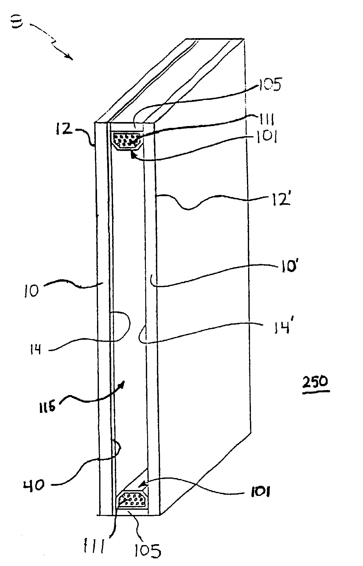
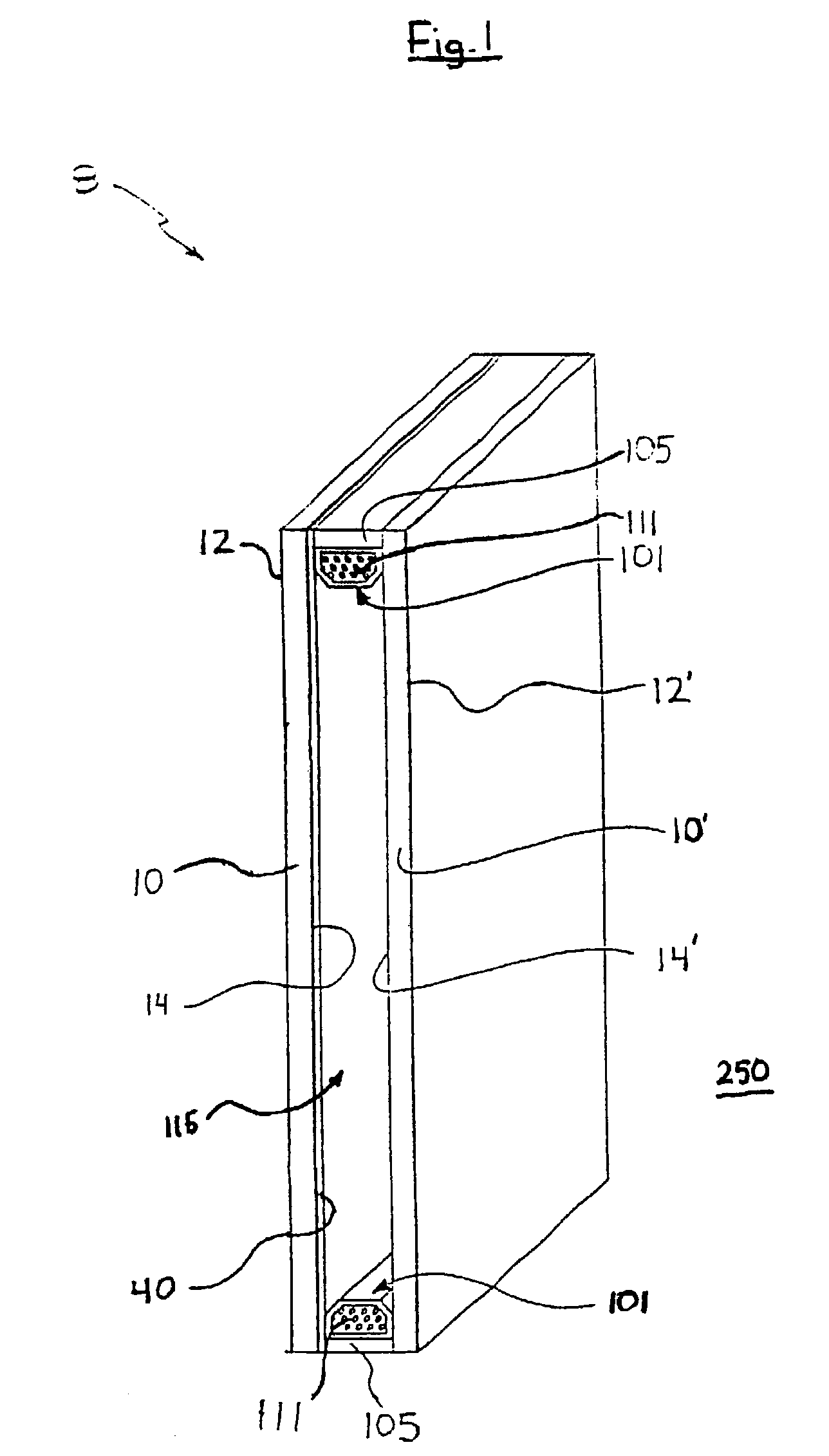
[0022]The following detailed description is to be read with reference to the drawings, in which like elements in different drawings have like reference numerals. The drawings, which are not necessarily to scale, depict selected embodiments and are not intended to limit the scope of the invention. Skilled artisans will recognize that the examples provided herein have many useful alternatives that fall within the scope of the invention.

[0023]A variety of substrates are suitable for use in the present invention. In most cases, the substrate 10 is a sheet of transparent material (i.e., a transparent sheet). However, the substrate 10 is not required to be transparent. For example, opaque substrates may be useful in some cases. However, it is anticipated that for most applications, the substrate will comprise a transparent or translucent material, such as glass or clear plastic. In many cases, the substrate 10 will be a glass pane. A variety of known glass types can be used, and soda lime...


PUM

PropertyMeasurementUnit
optical thicknessaaaaaaaaaa

Abstract

The invention provides low solar reflectance, low-emissivity coatings. The invention also provides a pane bearing a low solar reflectance, low-emissivity coating. Further, the invention provides an insulating glass unit comprising first and second panes held in a spaced-apart configuration, wherein the panes have confronting inner surfaces oriented toward a between-pane space and opposed outer surfaces oriented away from the between-pane space, and wherein one of these inner surfaces bears a low solar reflectance, low-emissivity coating. Also provided are methods of producing coated substrates.

Description

CROSS-REFERENCE TO RELATED APPLICATIONS[0001]This application claims priority to U.S. Patent Application No. 60 / 411,031 filed on Sep. 16, 2002, and U.S. Patent Application No. 60 / 376,826 filed on Apr. 29, 2002, the entire disclosure of each of which is hereby incorporated by reference.FIELD OF THE INVENTION[0002]The present invention provides coatings for glass and other substrates. More particularly, this invention provides low-emissivity coatings that have low solar reflectance. The invention also provides methods for producing coatings of this nature, as well as insulating glass units and monolithic panes carrying these coatings.BACKGROUND OF THE INVENTION[0003]Windows can reflect a surprising amount of solar radiation. In some cases, this reflected radiation can become problematic. A certain amount of energy is, of course, carried in the solar radiation reflected off the exterior of a window. When this radiation falls on a nearby surface, the surface can be discolored. While thi...

Claims


Application Information

Patent Timeline
Patent Type & Authority Patents(United States)
IPC IPC(8): B32B17/06B05D5/06C03C17/00C03C17/36C03C27/06E06B5/00G02B5/28
CPCC03C17/002C03C17/36C03C17/3615C03C17/3618C03C17/3631C03C17/3639C03C17/3649C03C17/3652C03C17/366C03C17/3681G02B5/282C03C17/3644Y10T428/265C03C2217/78
Inventor HOFFMAN, WAYNE L.
Owner CARDINAL CG
Why Eureka
Try Eureka