[0012] In certain embodiments, the low-emissivity coating further comprises a transparent dielectric base coat between the substrate and the corrosion-resistant inner infrared-reflective layer. This transparent base coat typically comprises a durable transparent dielectric layer positioned directly beneath the corrosion-resistant inner-infrared reflective layer. Preferably, the durable transparent dielectric layer comprises a desired metal other than zinc. This desired metal can be a metal selected from the group consisting of tin, aluminum, bismuth, indium, titanium, niobium, and silicon. In some cases, the durable transparent dielectric layer comprises both zinc and the desired metal. For example, the durable transparent dielectric layer can comprise a major portion of zinc oxide and a minor portion of an oxide of the desired metal. Perhaps optimally, the durable transparent dielectric layer comprises zinc tin oxide and / or zinc aluminum oxide. In some cases, atoms of the desired metal account for less than about 10 atomic percent of the total metal atoms in the durable transparent dielectric layer. In some embodiments, the low-emissivity coating further comprises a transparent dielectric outer coat further from the substrate than the outer infrared-reflective layer.
[0013] In certain particularly preferred embodiments, the invention provides a substrate bearing a low-emissivity coating comprising, in sequence outwardly, a transparent base layer, a transparent dielectric base coat, a corrosion-resistant inner infrared-reflective layer, a transparent dielectric middle coat, and an outer infrared-reflective layer. In these embodiments, the outer infrared-reflective layer consists essentially of silver and the corrosion-resistant inner infrared-reflective layer has a different composition than the outer infrared-reflective layer. Here, the silicon dioxide is deposited directly over the substrate. Conjointly, the transparent dielectric base coat comprises at least one transparent dielectric film. Further, the transparent dielectric middle coat includes at least five transparent dielectric intermediate layers. Preferably, though not necessarily, the silicon dioxide has a thickness of less than 100 Å. In some preferred embodiments, each of the transparent dielectric intermediate layers has a thickness of less than 200 Å. In some cases, all the preferred features described in this paragraph are provided in combination and the transparent dielectric middle coat includes a layer consisting essentially of zinc oxide directly beneath the outer infrared-reflective layer and the transparent dielectric base coat includes a durable transparent dielectric layer directly beneath the corrosion-resistant inner infrared-reflective layer, the durable transparent dielectric layer comprising a desired metal, the desired metal being a metal other than zinc. In certain related methods, each layer / film described in this paragraph is deposited by a conventional sputtering method.
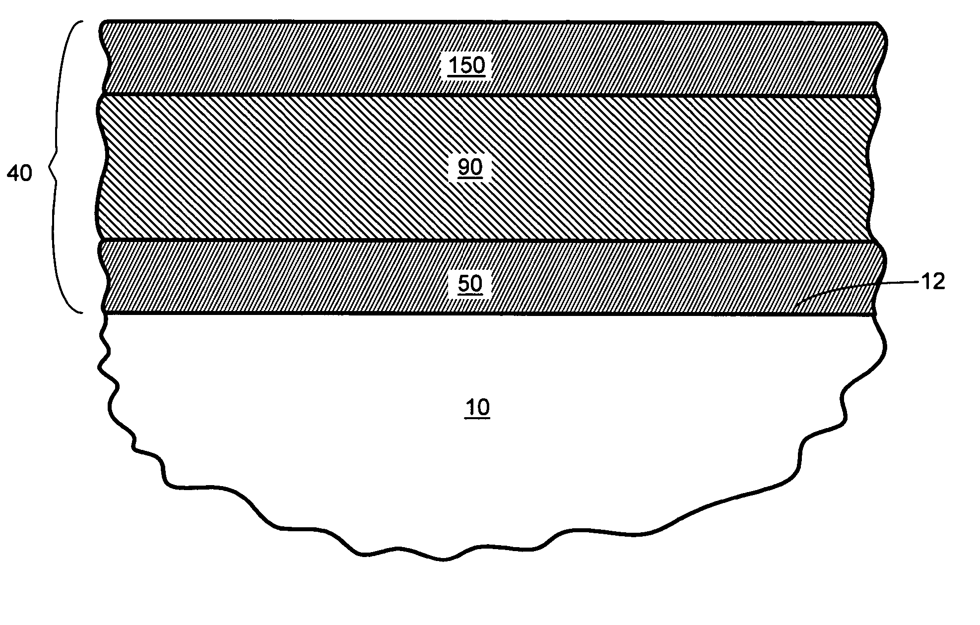
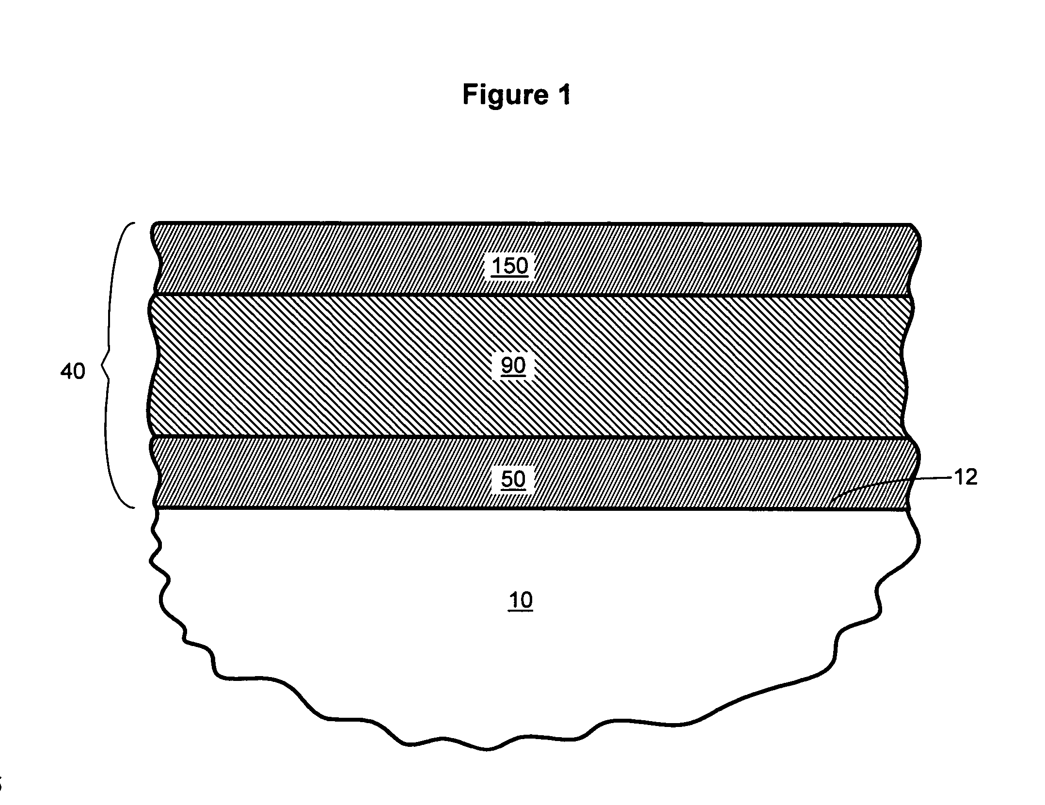
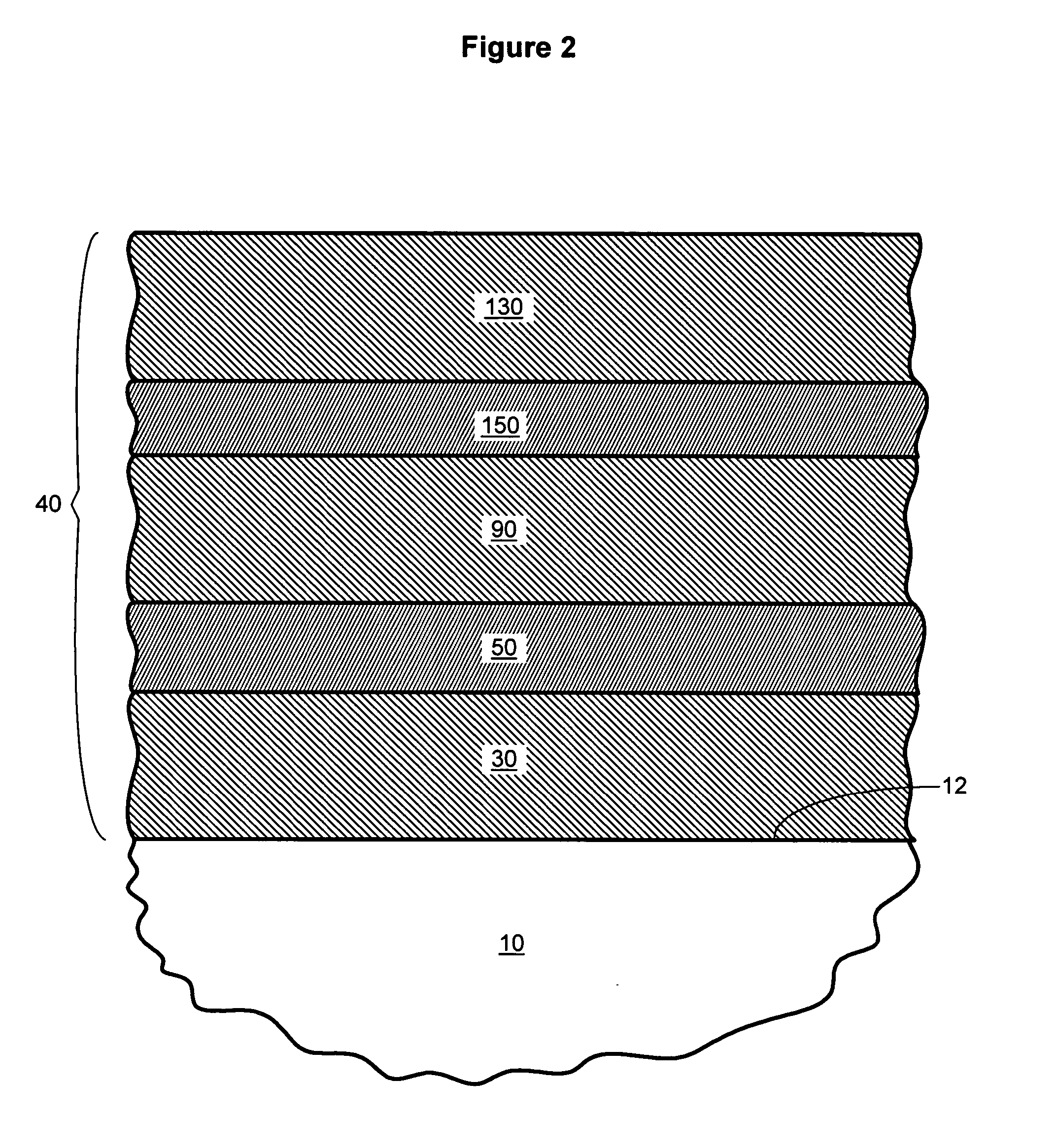
[0014] The invention also provides methods of producing coated substrates, e.g., by depositing a low-emissivity coating on a substrate. Typically, the method comprises providing a substrate having a surface, and depositing the low-emissivity coating onto this surface. Preferably, this involves depositing a low-emissivity coating comprising, moving outwardly from the substrate, a corrosion-resistant inner infrared-reflective layer, a transparent dielectric middle coat, and an outer infrared-reflective layer. Typically, the outer infrared-reflective layer is deposited as a film consisting essentially of silver and the inner infrared-reflective layer is deposited as a film having a different composition than the outer infrared-reflective layer. Preferably, the deposition of the transparent dielectric middle coat includes depositing a layer consisting essentially of zinc oxide directly beneath the outer infrared-reflective layer. In some cases, this zinc oxide layer is deposited at a thickness of at least about 40 angstroms. In certain favored methods, the middle coat is formed by deposited at least five intermediate films (as described). In some of the present embodiments, the inner infrared-reflective layer is deposited as a film comprising a corrosion-resistant silver alloy. For example, the inner infrared-reflective layer can be deposited as a film comprising a major portion of silver and a minor portion of a durable metal, the durable metal being a metal other than silver. Here, the inner infrared-reflective layer is preferably deposited as a film wherein atoms of the durable metal account for less than about 10 atomic percent relative to the total number of metal atoms in the inner infrared-reflective layer. In some cases, the inner infrared-reflective layer is deposited as a film comprising silver and a durable metal selected from the group consisting of platinum, palladium, copper, nickel, gold, indium, zinc, silicon, boron, and beryllium. The inner infrared-reflective layer can alternatively be deposited as a film comprising an electrically-conductive nitride. When this is done, the deposition of the middle coat can optionally include depositing an oxide or nitride layer directly over the electrically-conductive nitride of the inner infrared-reflective layer. In some cases, the inner infrared-reflective layer is deposited as a film comprising an electrically-conductive nitride selected from the group consisting of chromium nitride, zirconium nitride, titanium nitride, and niobium nitride. If so desired, the present method can further comprise depositing a transparent dielectric base coat between the substrate and the corrosion-resistant inner infrared-reflective layer, the transparent dielectric base coat including a durable transparent dielectric layer directly beneath the corrosion-resistant inner infrared-reflective layer, the durable transparent dielectric layer comprising a desired metal, the desired metal being a metal other than zinc. For example, the durable transparent dielectric layer can be deposited as a film comprising a desired metal selected from the group consisting of tin, aluminum, bismuth, indium, titanium, niobium, and silicon Preferably, the durable transparent dielectric layer is deposited as a film comprising zinc and the desired metal. For example, the durable transparent dielectric layer can be deposited as a film comprising a major portion of zinc oxide and a minor portion of an oxide of the desired metal. In some cases, the durable transparent dielectric layer is deposited as a film wherein atoms of the desired metal account for less than about 10 atomic percent relative to the total number of metal atoms in the durable transparent dielectric layer. Perhaps optimally, the durable transparent dielectric layer is deposited as a film comprising zinc tin oxide and / or zinc aluminum oxide. In some cases, the method further comprises depositing a transparent dielectric outer coat further from the substrate than the outer infrared-reflective layer. Preferably, each layer in the coating is deposited on the substrate by sputtering.

