Portable survival shelter

a survival shelter and portable technology, applied in the field of survival shelters, can solve the problems of large adaptation and redesign of existing shelter designs, 42,000 missing, severe damage, etc., and achieve the effect of facilitating retrieval

Inactive Publication Date: 2007-11-01
WAGNER MICHAEL P
View PDF22 Cites 24 Cited by
  • Summary
  • Abstract
  • Description
  • Claims
  • Application Information

AI Technical Summary

Benefits of technology

[0008] In a preferred embodiment of the invention, a portable survival shelter includes a body having a generally elongated shape and a protective outer shell structure, a sealable entrance on the top of the body, and a base upon which the body is formed. The body defines a sealable survival chamber that is large enough to hold one or more persons and is strong enough to withstand the impact of falling tree limbs, flying debris, or the like. The survival shelter is particularly well suited for protecting one or more occupants from life threatening flood waters that may be associated with, for example, a storm surge or a tsunami.
[0009] In a preferred embodiment, the shelter is configured with ballast to float in water in an upright orientation and is constructed with an exterior surface substantially free from protruding snags so that the shelter more easily avoids becoming caught up in, for example, storm debris, and so that the shelter may be retrieved more easily by search and rescue personnel.

Problems solved by technology

The resulting tsunami devastated the shores of Indonesia, Sri Lanka, South India, Thailand, and other countries with waves up to 100 feet, claiming over 180,000 lives and leaving another 42,000 missing.
Also, Hurricanes Katrina and Rita struck the U.S. Gulf Coast on Aug. 29, 2005, and Sep. 24, 2005, respectively, causing severe damage from flooding due to a two-story storm surge, powerful winds, and heavy rains.
Taking shelter is critical in times of disaster.
However, a safe room is a structure built in a fixed location and is typically designed only for those hazardous conditions deemed likely to occur in the particular geographic area.
However, existing shelter designs need considerable adaptation and redesign for such use.
That is, prior shelter designs do not provide adequate portability or sufficient capabilities to provide effective shelter in a wide variety of situations.

Method used


Image

  • Portable survival shelter
  • Portable survival shelter
  • Portable survival shelter

Examples


Embodiment Construction

[0020] In the following detailed description, numerous specific details are set forth in order to provide a thorough understanding of the present invention. However, those skilled in the art will understand that the present invention may be practiced without these specific details, that the present invention is not limited to the depicted embodiments, and that the present invention may be practiced in a variety of alternative embodiments. In other instances, well known methods, procedures, components, and systems have not been described in detail.

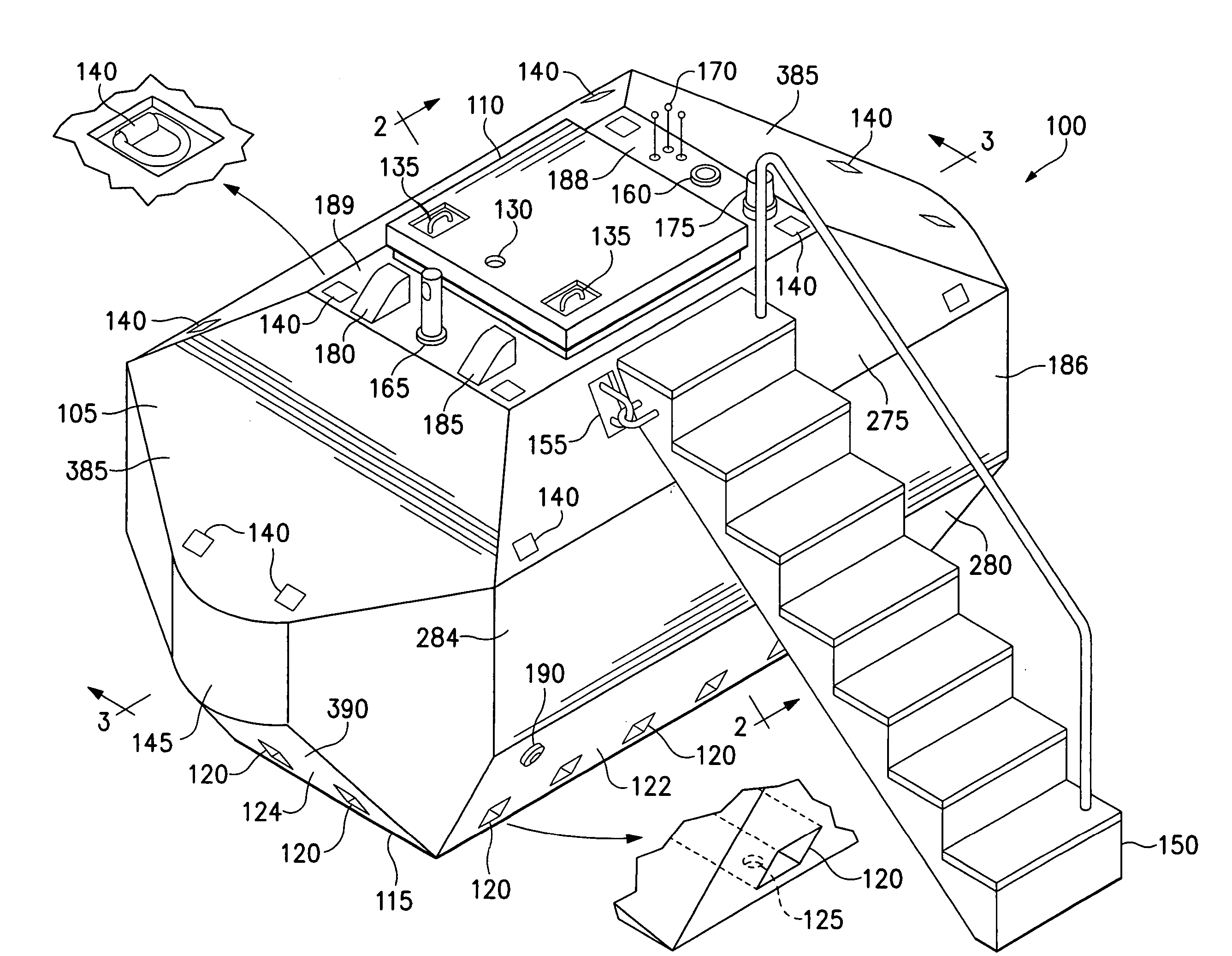
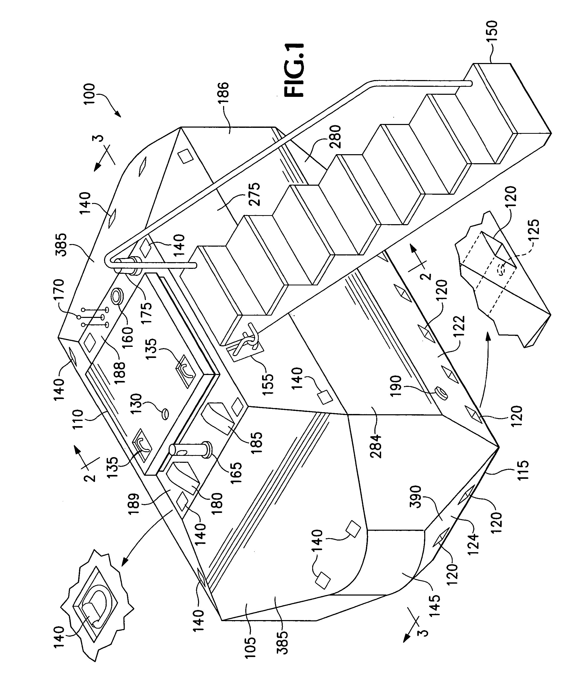
[0021] Turning now to the drawings, FIG. 1 is an isometric view of a survival shelter 100 according to one embodiment of the invention. The survival shelter 100, as shown, includes a body 105 having a generally elongated shape and a protective outer shell structure, a sealable entrance (or hatch) 110 on the top of the body 105, and a base 115 upon which the body 105 is formed. The body 105 defines a sealable survival chamber that is both l...


PUM


Abstract

A portable survival shelter that includes a body having a generally elongated shape and a protective outer shell structure, a sealable entrance on the top of the body, and a base upon which the body is formed. The body defines a sealable survival chamber that is large enough to hold one or more persons and strong enough to withstand the impact of falling tree limbs, flying debris, or the like. The shelter is preferably configured with ballast to float in water in an upright orientation and constructed with an exterior surface substantially free from protruding snags. The shelter is preferably of a size that fits within a conventional automobile garage, and preferably incorporates forklift pockets for moving the shelter from place to place with a forklift or recessed pad eyes for lifting the shelter with a crane or helicopter.

Description

BACKGROUND OF THE INVENTION [0001] The present invention relates to a survival shelter. More particularly, the present invention relates to a survival shelter for providing one or more persons refuge from hazardous conditions such as flooding, falling debris, and the like. [0002] Notorious natural disasters have underscored the need for improved sheltering. For example, the 2004 Indian Ocean earthquake, also known as the Asian Tsunami or Boxing Day Tsunami, was an undersea earthquake measuring between 9.1 and 9.3 (Richter scale) that occurred on Dec. 26, 2004. The resulting tsunami devastated the shores of Indonesia, Sri Lanka, South India, Thailand, and other countries with waves up to 100 feet, claiming over 180,000 lives and leaving another 42,000 missing. Also, Hurricanes Katrina and Rita struck the U.S. Gulf Coast on Aug. 29, 2005, and Sep. 24, 2005, respectively, causing severe damage from flooding due to a two-story storm surge, powerful winds, and heavy rains. More than 200,...

Claims


Application Information

Patent Timeline
Patent Type & Authority Applications(United States)
IPC IPC(8): E02D29/14
CPCE04H9/145Y02A10/30Y02A50/00
Inventor WAGNER, MICHAEL P.
Owner WAGNER MICHAEL P
Why Eureka
Try Eureka