Refrigerator rail system for removably supported side-sliding shelves

a refrigerator and rail system technology, applied in the field of refrigerator rail systems, can solve the problems of affecting assembly ease and production cost, and achieve the effect of easy customization of the inside of the refrigerator compartmen

Inactive Publication Date: 2007-11-01
MAYTAG
View PDF16 Cites 24 Cited by
  • Summary
  • Abstract
  • Description
  • Claims
  • Application Information

AI Technical Summary

Benefits of technology

[0006] The present invention is directed to a refrigerator shelving system for removably supporting side-sliding refrigerator shelves. The rail system includes first and second horizontally spaced rails positioned adjacent the back wall of a refrigerator compartment. Each rail includes a plurality of spaced-apart apertures formed therein for removably retaining a crossbar. A first end of the crossbar is inserted into an aperture in the first rail, while a second end of the crossbar is inserted into an aperture in the second rail. The crossbar can then be rotated within the apertures to a fixed, angled position with respect to the rails. Once the crossbar is fixed to the rails, a shelf, having at least one hook, can be mounted onto the crossbar so that the shelf extends from and is supported by the crossbar in a cantilevered fashion. When the shelf has a width that is less than that of the crossbar, the hook of the shelf can be slid along the crossbar to re-position the shelf horizontally within the refrigerator cabinet. Thus, this system allows one or more refrigerator shelves to be positioned in various horizontal and / or vertical positions within a refrigerator for easy customization of the inside of the refrigerator compartment.

Problems solved by technology

As with all rail systems for shelving units, the materials used and the design of the individual pieces of the system can greatly affect the ease of assembly and cost of production.

Method used


Image

  • Refrigerator rail system for removably supported side-sliding shelves
  • Refrigerator rail system for removably supported side-sliding shelves
  • Refrigerator rail system for removably supported side-sliding shelves

Examples


Embodiment Construction

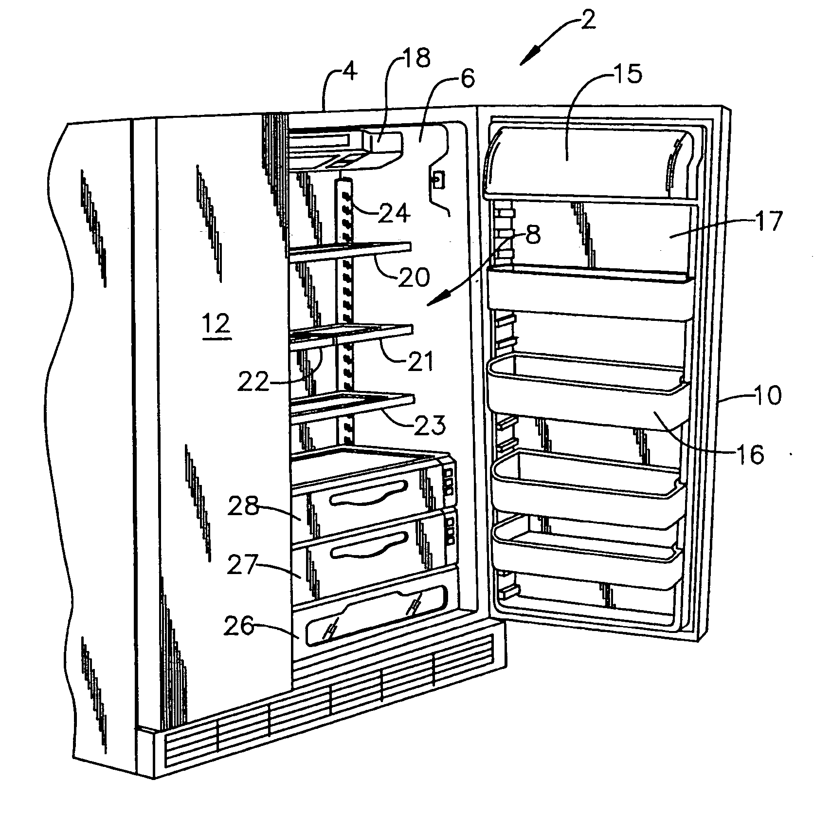
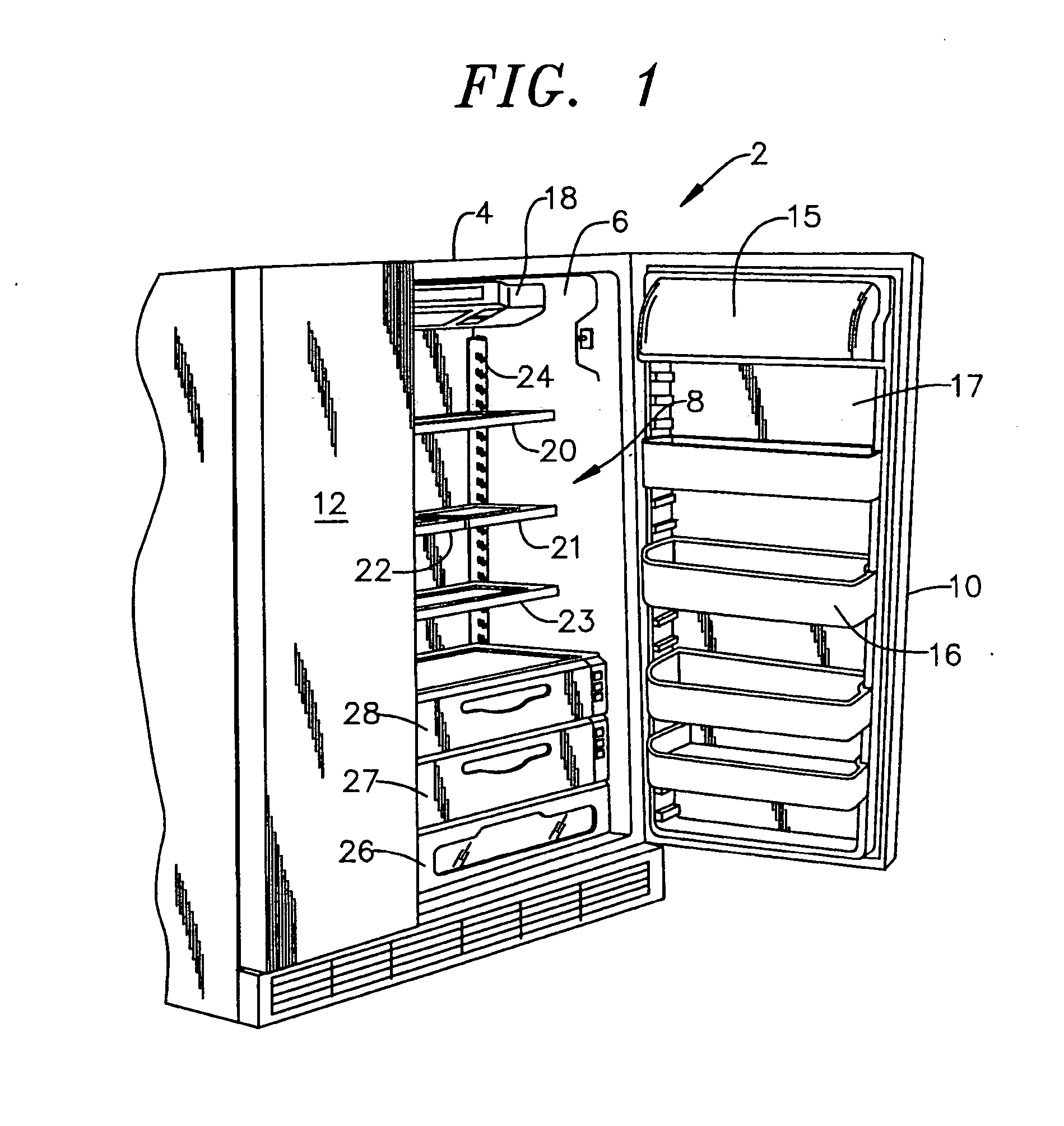
[0012] With initial reference to FIG. 1, a refrigerator cabinet 2 includes a cabinet shell 4 within which is positioned a liner 6 that defines a fresh food compartment 8. In a manner known in the art, fresh food compartment 8 can be accessed by the selective opening of a fresh food door 10. In a similar manner, a freezer door 12 can be opened to access a liner defined freezer compartment (not shown). For the sake of completeness, door 10 of refrigerator cabinet 2 is shown to include a dairy compartment 15 and various vertically adjustable storage units, one of which is indicated at 16. As shown, storage unit 16 constitutes a pick-off bucket that can be selectively removed from a liner 17 of door 10. Mounted in an upper region of fresh food compartment 8 is a temperature control housing 18 which, in a manner known in the art, can be used to regulate the temperature in both fresh food compartment 8 and the freezer compartment. Below temperature control housing 18 are arranged a plural...


PUM


Abstract

A repositionable rail system for a refrigerator includes first and second rails, each rail having a plurality of spaced-apart apertures. A crossbar has first and second ends adapted to fit within respective apertures on the first and second rails. After inserting the crossbar into the apertures, the crossbar is rotated to a fixed angled position. A half-width shelf having a hook is adapted to removably supported, in a cantilevered manner, by the crossbar. The half-width shelf can be slid along the crossbar for repositioning within the refrigerator cabinet, or may be placed alongside another half-width shelf on a crossbar, or replaced with a full width shelf mounted on the first and second rails in a corresponding, cantilevered manner.

Description

BACKGROUND OF THE INVENTION [0001] 1. Field of the Invention [0002] The present invention pertains to the art of refrigerator shelving systems and, more specifically, to a refrigerator rail system for removably supporting side-sliding refrigerator shelves. [0003] 2. Discussion of the Prior Art [0004] Many different types of shelving systems have been provided for refrigerator compartments. For example, it is common to provide vertically adjustable storage units and / or shelves in refrigerator cabinets in order to increase the versatility of storing a wide range of food items. To this end, many fresh food compartments have elongated, vertically extending and laterally spaced rails or tracks mounted on rear walls thereof, with the rails enabling storage units to be supported in selected vertically adjustable positions in a cantilevered manner. Typical rails of this type include a plurality of spaced slots into which storage unit hooks can be inserted to support the units in a cantileve...

Claims


Application Information

Patent Timeline
Patent Type & Authority Applications(United States)
IPC IPC(8): A47B96/04
CPCF25D25/02
Inventor WING, FORREST F.
Owner MAYTAG
Why Eureka
Try Eureka