Blower motor for HVAC systems

Active Publication Date: 2011-10-27
NIDEC MOTOR CORP
View PDF1 Cites 12 Cited by
  • Summary
  • Abstract
  • Description
  • Claims
  • Application Information

AI Technical Summary

Benefits of technology

Another embodiment of the invention provides methods to adjust the torque settings of an HVAC blower motor. HVAC OEMs often desire blower motors specifically designed to work with their HVAC equipment. With PSC motors, motor manufacturers can accommodate such requests by changing the motor winding taps on their motors to achieve the desired torque ratings. Unfortunately, changing the motor winding taps to accommodate every OEM's exact specifications is time-consuming and costly and requires that many slightly modified motors be manufactured and stocked. The present invention makes it easier to customize HVAC motors for particular OEMs' needs, by providing a simple method of adjusting the torque values of a blower motor without changing the motor's winding taps or otherwise altering the motor's physical design. In particular, the torque values of the motor may be modified during manufacturing without the use of a computer or other device capable of individually changing all of the torque memory values stored in the motor memory. Instead, the torque values are automatically modified in the motor based upon a single maximum torque desired in the motor, as described herein.
By constructing a blower motor assembly as

Problems solved by technology

However, the blower motors used to move the air in these systems have not seen significant efficiency improvements and have much lower efficiencies.
Blower motor inefficiencies are magnified when a blower motor is operated for extended hours beyond that needed solely for heating and cooling.
This causes excess energy usage and noise.
In addition, with the blower switch in the “on” position, the unit no longer is able to select the system speed for cooling or heating and instead continuously runs at the continuous fan speed.
The increased operation time therefore leads to greater energy use.
Many of the above-described inefficiencies result from the type of blower motor used in HVAC systems.
Because air conditioner evaporator coils need higher airflow than furnace heat exchangers, the blower motor operates at a lower speed during furnace operation, where it is less efficient, and at an even lower speed still during continuous fan “on” operation, where it is least efficient.
While variable speed motors are oft

Method used


Image

  • Blower motor for HVAC systems
  • Blower motor for HVAC systems
  • Blower motor for HVAC systems

Examples


Embodiment Construction

The following detailed description of the invention references the accompanying drawings that illustrate specific embodiments in which the invention can be practiced. The embodiments are intended to describe aspects of the invention in sufficient detail to enable those skilled in the art to practice the invention. Other embodiments can be utilized and changes can be made without departing from the scope of the invention. The following detailed description is, therefore, not to be taken in a limiting sense. The scope of the invention is defined only by the appended claims, along with the full scope of equivalents to which such claims are entitled.

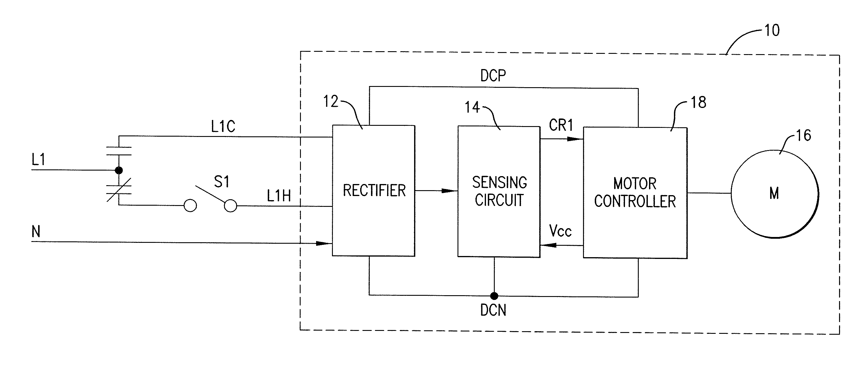
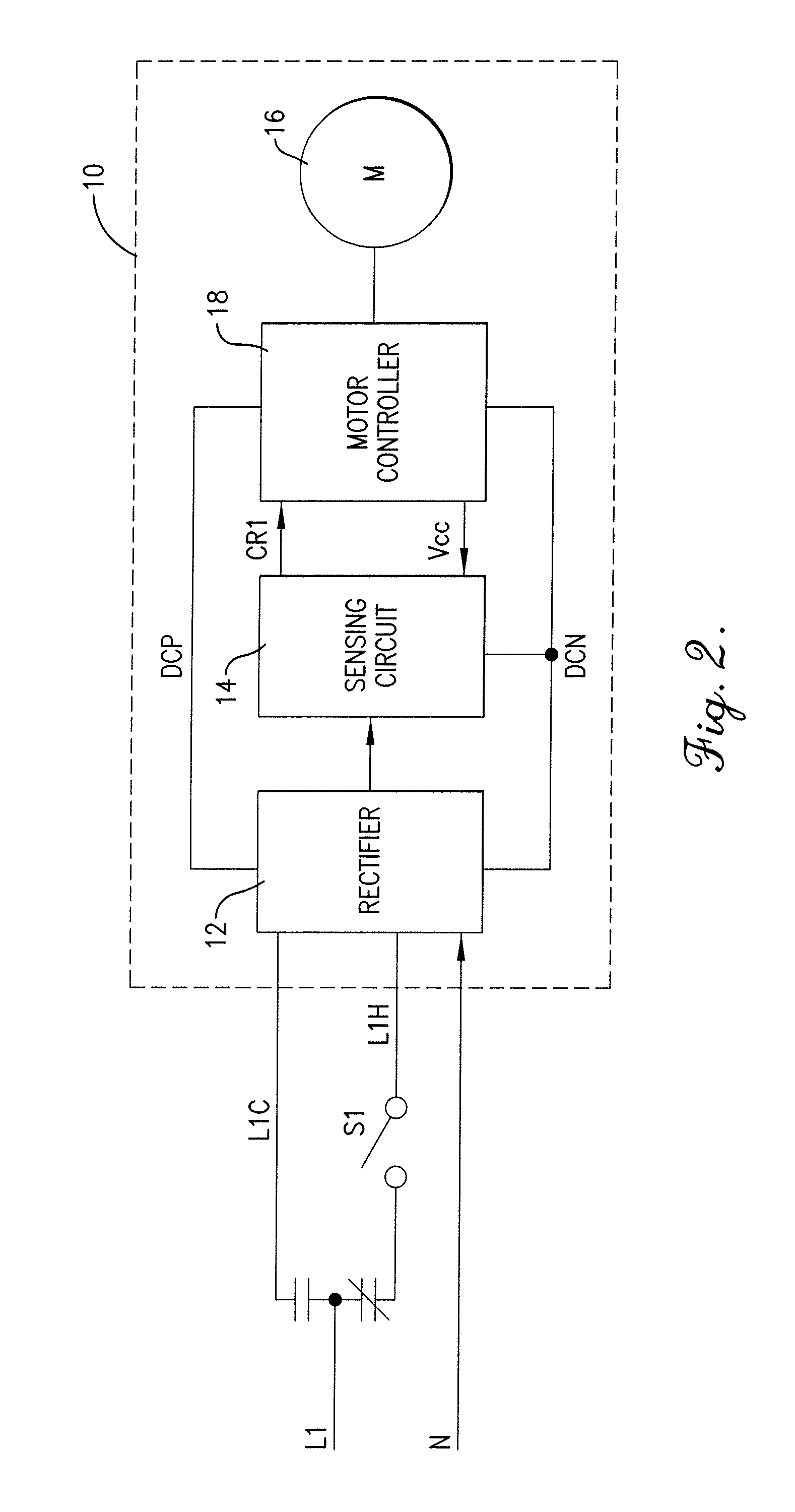
Referring now to FIG. 2, a blower motor assembly 10 constructed in accordance with an embodiment of the invention is shown. The illustrated blower motor assembly 10 broadly comprises a rectifier 12, a novel sensing circuit 14, a variable speed motor 16, and the motor's associated motor controller and power converter 18. Power to the blower m...


PUM


Abstract

A blower motor assembly having a variable speed motor that is suitable for direct, drop-in replacement in a residential HVAC (heating, ventilation, and air conditioning) system that employs a PSC motor. The blower motor assembly includes at least a neutral input and two hot AC line connections, one for connection to the heating power source and the other to the cooling power source. A sensing circuit senses which of the inputs is energized by sensing either voltage or current on the inputs. The sensing circuit delivers a corresponding signal to a motor controller to control the speed of the variable speed motor. The blower motor assembly may also be equipped with additional hot AC inputs, more than one neutral line, and several sensing circuits for sensing current or voltage in the hot inputs and/or the neutral lines for controlling various aspects of the variable speed motor.

Description

FIELD OF INVENTIONThe present invention relates to blower motors and controls used in residential heating, ventilation, and air conditioning (HVAC) systems. More particularly, embodiments of the invention relate to a replacement blower motor assembly that can be connected to the standard power terminals used for a permanent split capacitor (PSC) motor and such a blower motor assembly that can be used in Original Equipment Manufacturer (OEM) applications and other applications.BACKGROUNDHVAC system efficiency increases have provided considerable reductions in energy use. For example, many high efficiency furnaces, air conditioners, and air handlers now have efficiencies (AFUE ratings) greater than 90%. However, the blower motors used to move the air in these systems have not seen significant efficiency improvements and have much lower efficiencies. As furnaces and air conditioners have become more efficient, the fraction of total energy consumption for HVAC systems attributed to the ...

Claims


Application Information

Patent Timeline
IPC IPC(8): H02P7/06
CPCH02P6/08
Inventor WOODWARD, ARTHUR E.
Owner NIDEC MOTOR CORP
Why Eureka
Try Eureka