Skate suspension system and method of assembly

a suspension system and skate technology, applied in the field of skates with vertical suspension, can solve the problems of general concept that fails to contemplate the manufacturing and quality issues associated with spring compression and containment within the blade housing, and general concept fails to contemplate the desire for adjustable and variable suspension settings, so as to achieve the effect of easily customizing the suspension system characteristics and altering the compression characteristics of the suspension system

Inactive Publication Date: 2013-10-31
BLOIS DAVID A
View PDF6 Cites 13 Cited by
  • Summary
  • Abstract
  • Description
  • Claims
  • Application Information

AI Technical Summary

Benefits of technology

[0009]According to another aspect of the present invention, a blade assembly for an ice skate has a retainer plate coupled with a top surface of a blade housing to provide a means for compressing and retaining a spring within the blade housing without attaching a skate boot. The retainer plate may also be adapted to include a spacer between the spring and the retainer plate to alter the compression characteristics of the suspension system. Further, the spacer may be adjustable to compress or decompress the spring for easily customizing the suspension system characteristics for a user's desired suspension performance.

Problems solved by technology

An ice skate with a novel concept of providing a suspension system between the skate boot and the blade to further improve power transfer is generally disclosed in Canadian Patent No. 2,324,724 to David A. Blois. However, the previously disclosed general concept fails to contemplate the manufacturing and quality issues associated with spring compression and containment within the blade housing.
Further, the general concept fails to contemplate a desire for adjustable and variable suspension settings that provide a skater with alternative suspension characteristics.

Method used


Image

  • Skate suspension system and method of assembly
  • Skate suspension system and method of assembly
  • Skate suspension system and method of assembly

Examples


Embodiment Construction

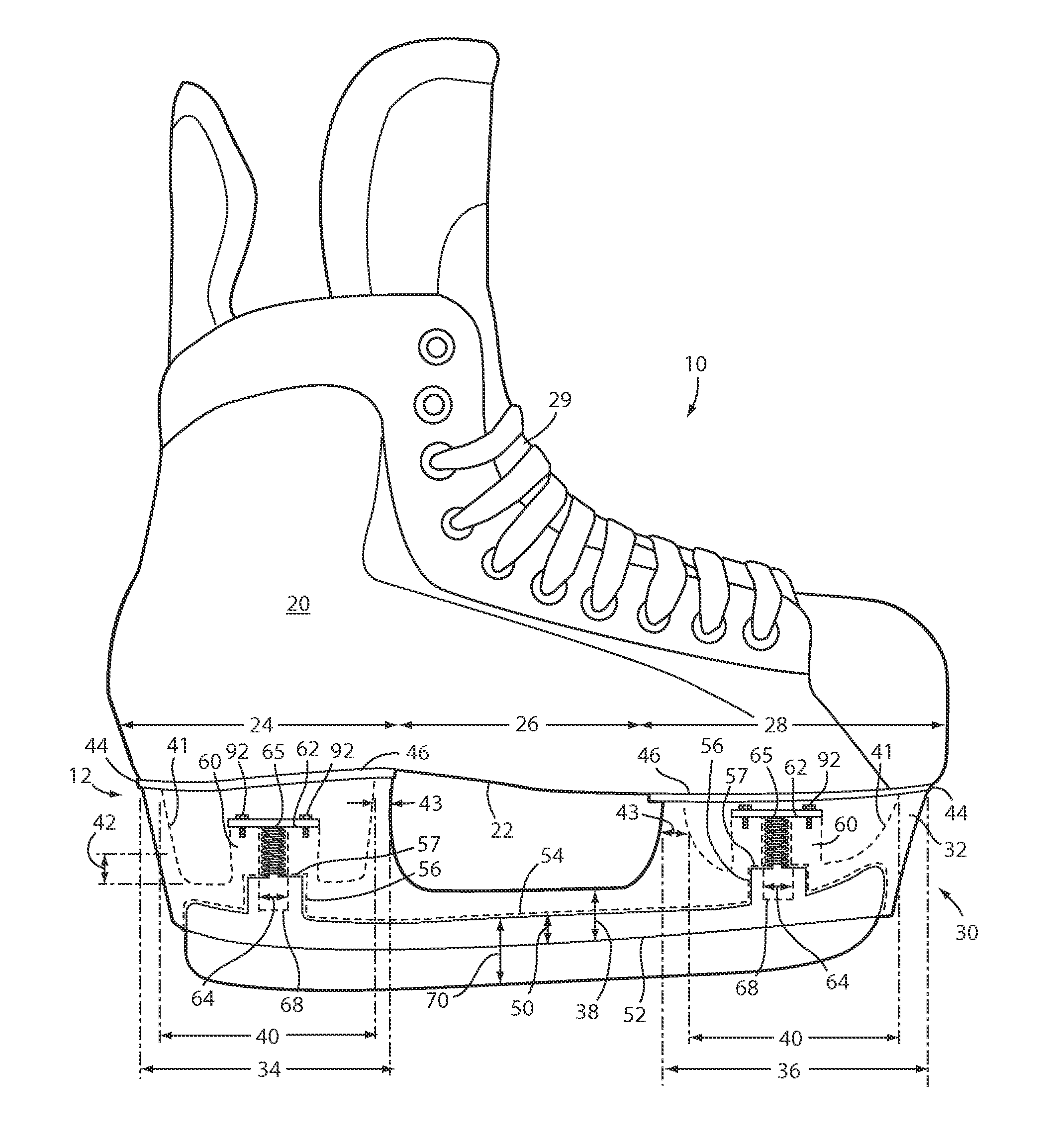
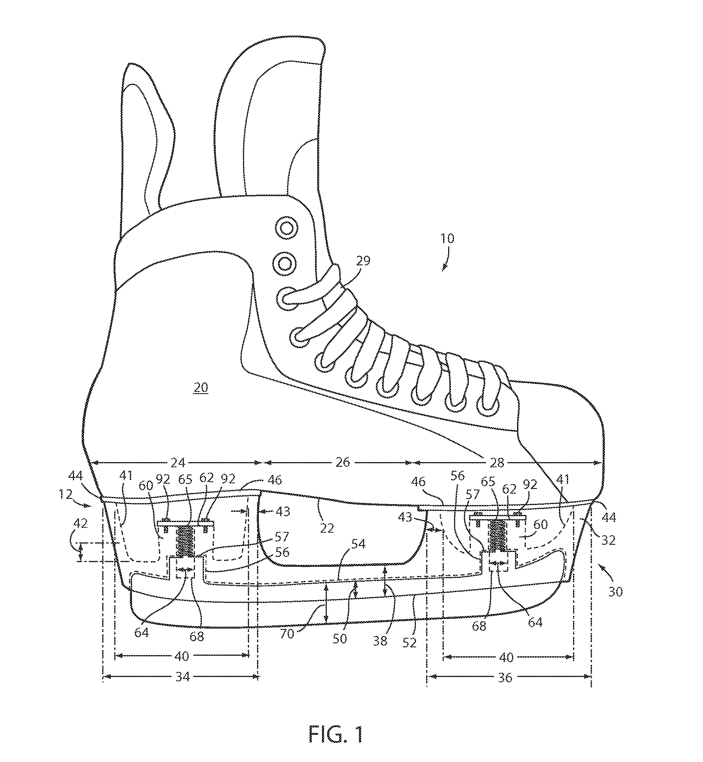
[0023]For purposes of description herein, the terms “upper,”“lower,”“right,”“left,”“rear,”“front,”“vertical,”“horizontal,” and derivatives thereof shall relate to the invention as oriented in FIG. 1. However, it is to be understood that the invention may assume various alternative orientations, except where expressly specified to the contrary. It is also to be understood that the specific devices and processes illustrated in the attached drawings, and described in the following specification are simply exemplary embodiments of the inventive concepts defined in the appended claims. Hence, specific dimensions and other physical characteristics relating to the embodiments disclosed herein are not to be considered as limiting, unless the claims expressly state otherwise.

[0024]Referring generally to FIGS. 1-7B, reference numeral 10 generally designates a skate with a suspension system. The skate 10 includes a boot 20 and a base assembly 30 having a top portion 12 coupled with a sole surf...


PUM

PropertyMeasurementUnit
sizeaaaaaaaaaa
heightaaaaaaaaaa
heightaaaaaaaaaa

Abstract

A skate includes a boot and a housing having a top portion coupled with a sole of the boot. A ground engagement apparatus is displaceably coupled with a bottom portion of the housing. A suspension assembly is coupled between the ground engagement apparatus and the housing. The suspension assembly includes an aperture extending down from the top portion of the housing. The suspension assembly also includes a spring disposed within the aperture, such that a lower portion of the spring engages the ground engagement apparatus. A retention member spans over the aperture and couples with the top portion of the housing, whereby an upper portion of the spring engages the retention member for retaining the spring within the aperture and biasing the ground engagement apparatus downward.

Description

CROSS-REFERENCE TO RELATED APPLICATION[0001]This application claims benefit under 35 USC §119(e) of provisional application Ser. No. 61 / 640,213, filed Apr. 30, 2012, entitled SUSPENSION SYSTEM FOR AN ICE SKATE BLADE the entire contents of which are incorporated herein by reference.FIELD OF THE INVENTION[0002]The present invention generally relates to skates with vertical suspension and more particularly relates to ice skates that have a suspension system for the blade that is enclosed within the blade housing.BACKGROUND OF THE INVENTION[0003]Ice skates are typically rigid in construction with respect to the connection between the skate boot and the blade. Accordingly, emphasis in innovation has generally been focused on optimizing flexure characteristics and reducing weight in the skate boot to provide improved power transfer of a skater's stride. An ice skate with a novel concept of providing a suspension system between the skate boot and the blade to further improve power transfer...

Claims


Application Information

Patent Timeline
Patent Type & Authority Applications(United States)
IPC IPC(8): A63C1/30A63C1/42
CPCA63C1/30A63C1/42Y10T29/49863A63C1/303A63C2203/20
Inventor BLOIS, DAVID A.
Owner BLOIS DAVID A
Why Eureka
Try Eureka