Projection type display apparatus

a display apparatus and projection type technology, applied in the direction of projectors, optics, instruments, etc., can solve the problems of degrading image quality, reducing reducing the thinning of display apparatus, so as to reduce the depth dimension of projection type display apparatus, reduce the depth dimension, and reduce the effect of image quality

Inactive Publication Date: 2007-11-01
MITSUBISHI ELECTRIC CORP
View PDF6 Cites 15 Cited by
  • Summary
  • Abstract
  • Description
  • Claims
  • Application Information

AI Technical Summary

Benefits of technology

[0013] With such an arrangement, it becomes possible to reduce the depth dimension of the proj

Problems solved by technology

However, in order to shorten the distance from the power mirror to the screen, it is necessary to widen the angle of view of a projected light from the power mirror, with the result that the curvature of the power mirror becomes large.
Therefore, the display apparatus disclosed in the Patent Documents 1 through 3 has a problem that the thinning of the display apparatus is limited by the depth dimension of the power lens itself.
However, when the power mirror having an aspheric surface or a free

Method used


Image

  • Projection type display apparatus
  • Projection type display apparatus
  • Projection type display apparatus

Examples


embodiment 1

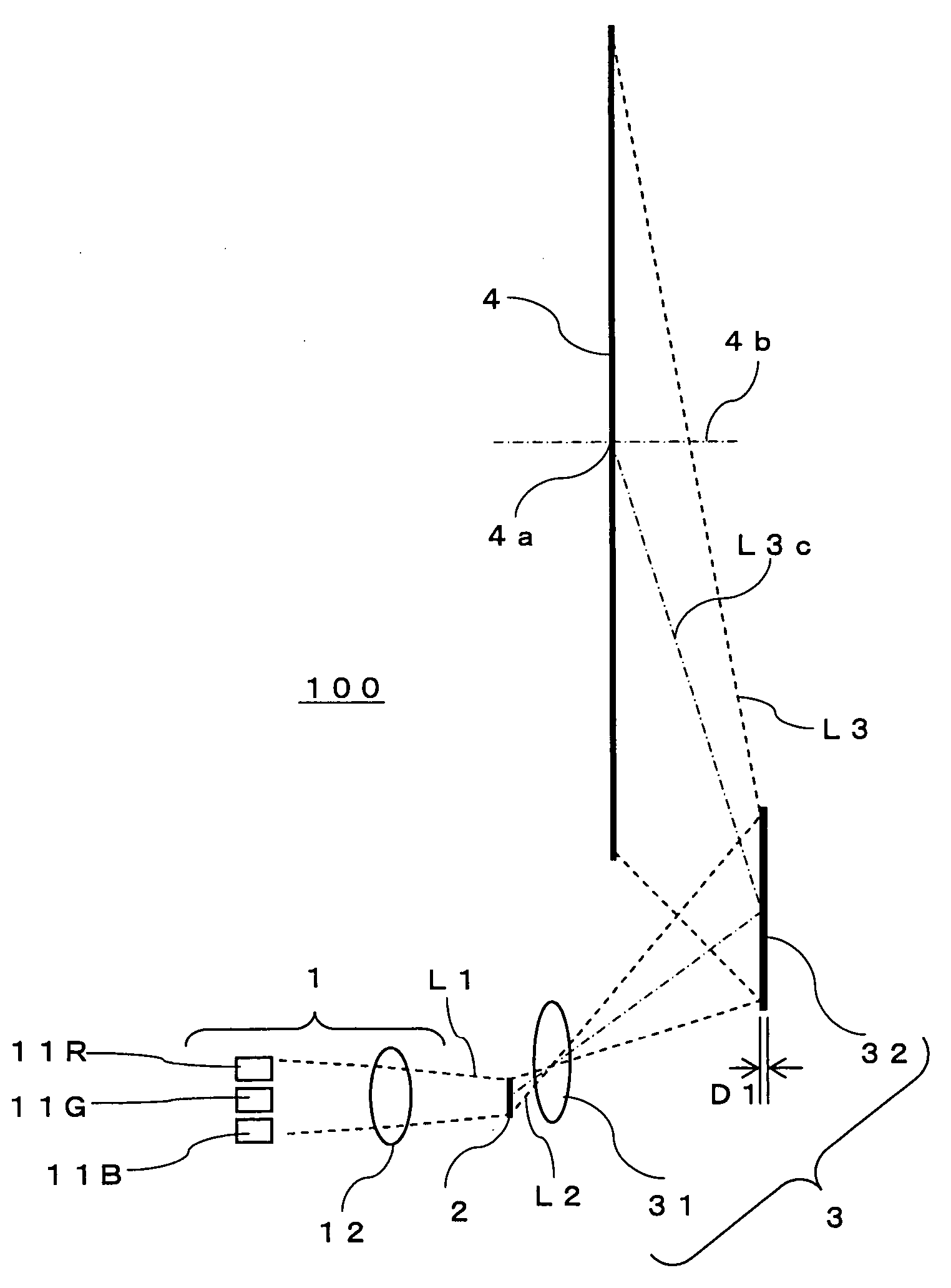
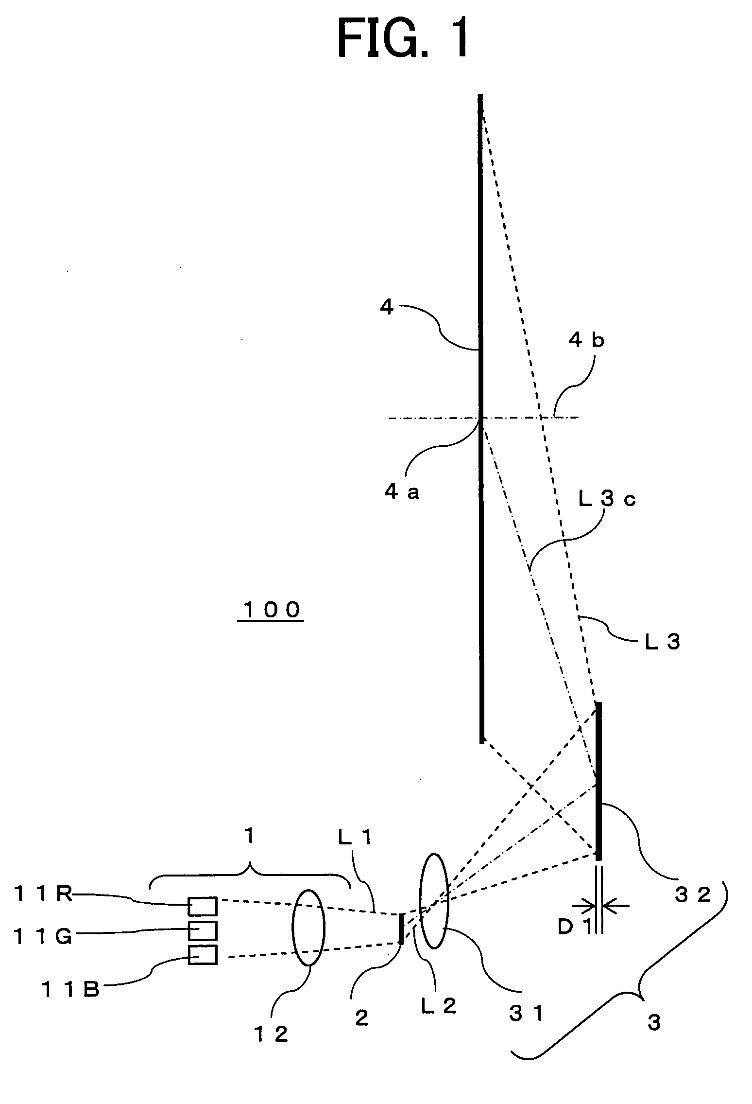
[0022]FIG. 1 is a side view schematically showing a configuration and a light path of a projection type display apparatus 100 according to Embodiment 1 of the present invention. The projection type display apparatus 100 is, for example, a rear projection television. FIG. 1 shows the interior of the projection type display apparatus 100 as seen from the side.

[0023] As shown in FIG. 1, the projection type display apparatus 100 according to Embodiment 1 includes an illumination device 1, a light modulation element (i.e., a light valve) 2 to which image signal is inputted and which modulates a light L1 from the illumination device 1 according to the image signal, a projection optical system 3 that projects the modulated light L2 from the light modulation element 2 in an enlarged manner, and a screen 4 onto which the projected light L3 from the projection optical system 3 is projected.

[0024] The illumination device 1 includes a plurality of laser light sources 11R, 11G and 11B and an i...


PUM


Abstract

In a projection type display apparatus includes an illumination device (including a light source), a light modulation element, a projection optical system that projects a modulated light from the light modulation element, and a screen onto which a projected light is projected. The projection optical system includes a refraction type optical system that refracts the modulated light from the light modulation element, and a hologram element disposed on a position remote from the screen and shifted in a direction parallel to the screen from a center of the screen. The hologram element projects the modulated light having passed through the refraction type optical system onto the screen so that a light ray of the center of the modulated light is inclined with respect to a normal line of the screen.

Description

BACKGROUND OF THE INVENTION [0001] This invention relates to a projection type display apparatus that projects an image formed by a light modulation element onto a screen in an enlarged manner. [0002] Conventionally, there is proposed a display apparatus configured to use a power mirror to obliquely project an image formed by a light valve (as a light modulation element) onto a screen in an enlarged manner (see, for example, Patent Documents 1 through 3). [0003] Further, there is proposed a display apparatus configured to use a hologram sheet to cause a light from a projection device to be incident on a screen at an angle approximately perpendicular to the screen (see, for example, Patent Document 4). [0004] Patent Document 1: Japanese Laid-Open Patent Publication No. 2004-157560 (FIG. 1) [0005] Patent Document 2: Japanese Laid-Open Patent Publication No. 2002-207168 (FIG. 39) [0006] Patent Document 3: International Publication No. 01 / 06295 (FIG. 20) [0007] Patent Document 4: Japane...

Claims


Application Information

Patent Timeline
IPC IPC(8): G03B21/14
CPCG03B21/62G03B21/28
Inventor KUWATA, MUNEHARUSASAGAWA, TOMOHIRO
Owner MITSUBISHI ELECTRIC CORP
Why Eureka
Try Eureka