Molded Micro-Needles

Inactive Publication Date: 2007-11-01
BONSENS
View PDF21 Cites 13 Cited by
  • Summary
  • Abstract
  • Description
  • Claims
  • Application Information

AI Technical Summary

Benefits of technology

[0008] Thus, the object of the present invention is to provide a method of manufacturing micro-needles ov

Problems solved by technology

These prior art devices and methods, while contributing to the development of the technology, still suffer from some drawbacks.
The device according to WO 03/015860 A1 requires bulk etching of material, which means that the cost of manufacture is affected by the use of excess material, i.e. large quantities of the bulk material must be removed to yield an array of microneedles.
This may result in long fabrication and process times and thus in

Method used


Image

  • Molded Micro-Needles
  • Molded Micro-Needles
  • Molded Micro-Needles

Examples


first embodiment

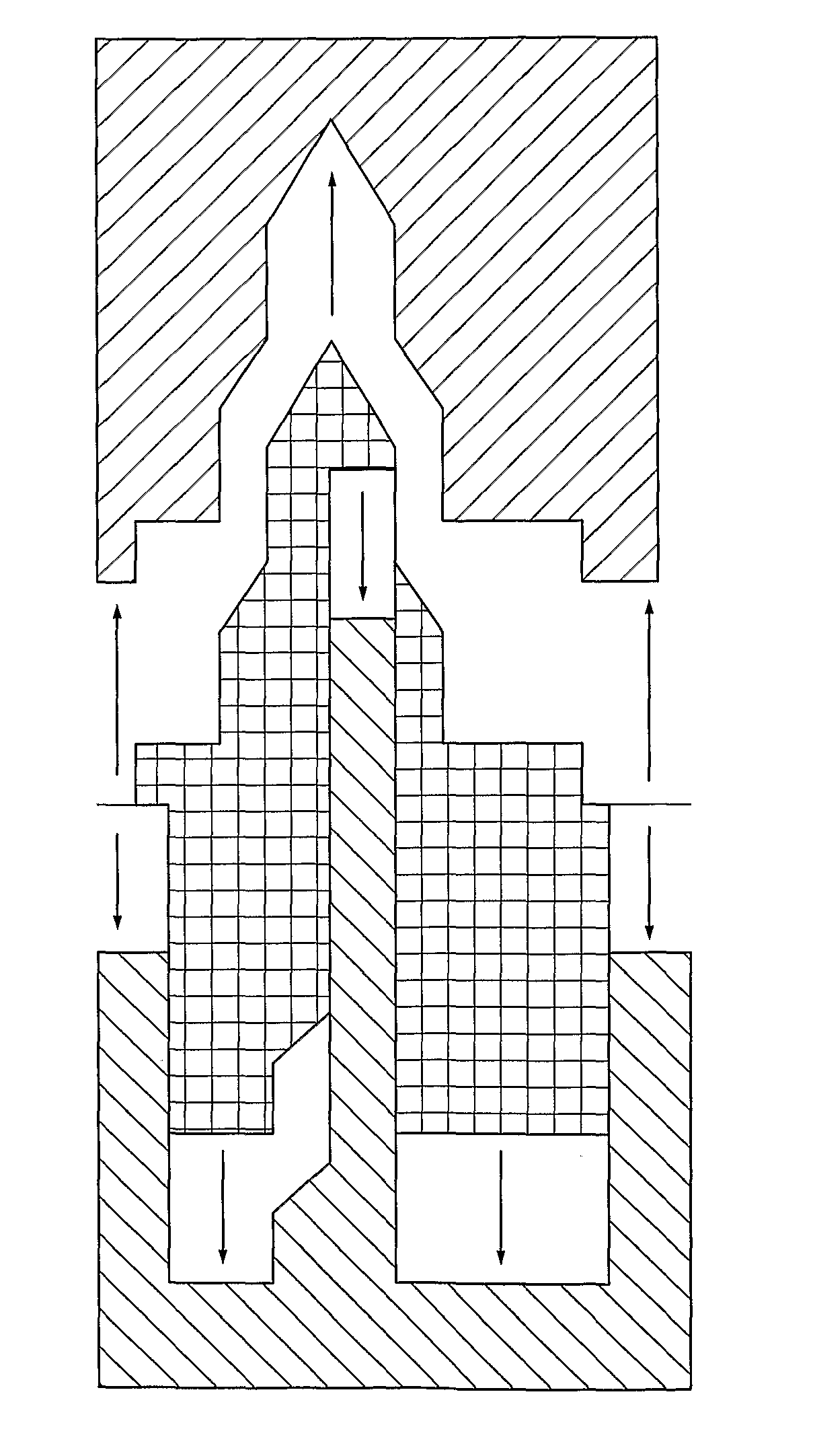
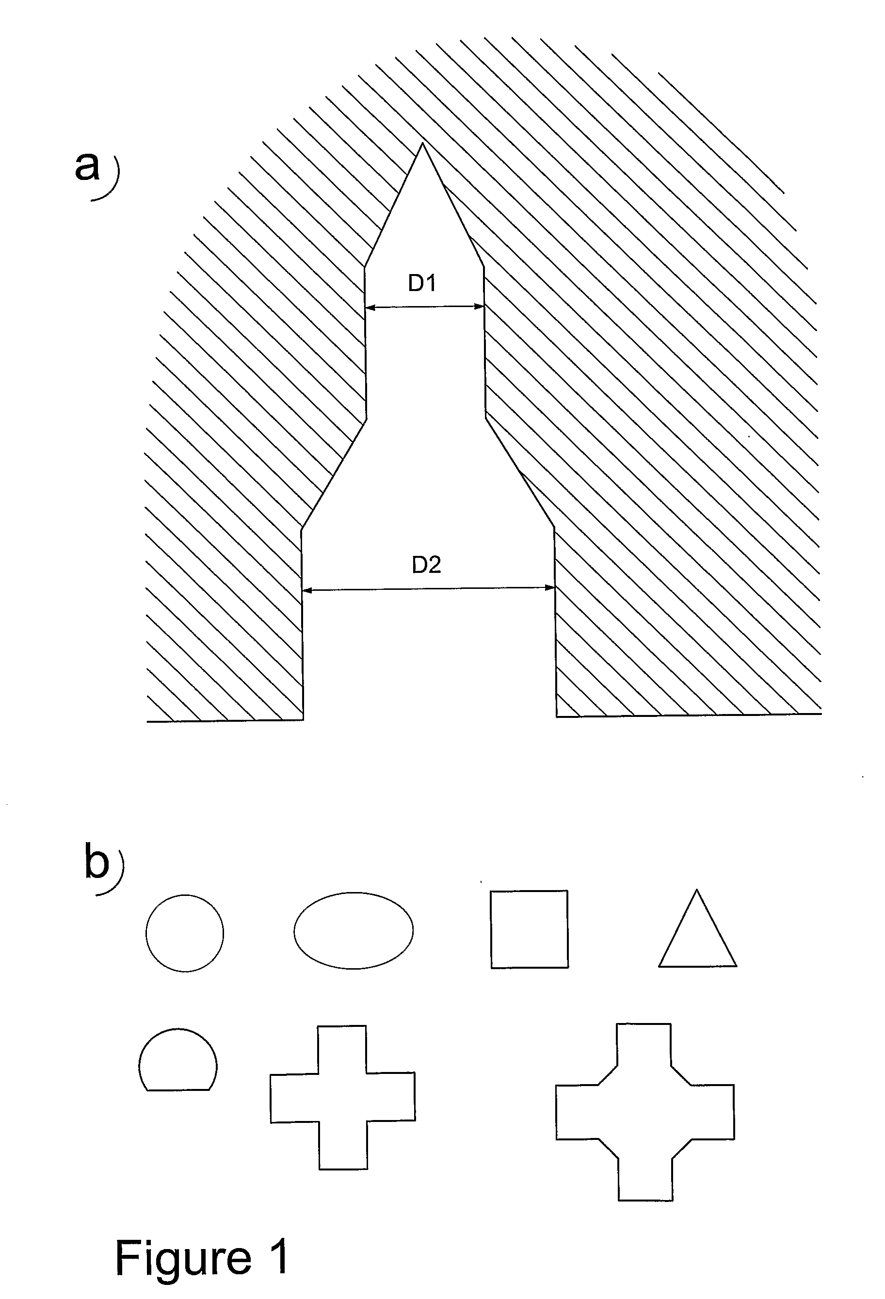
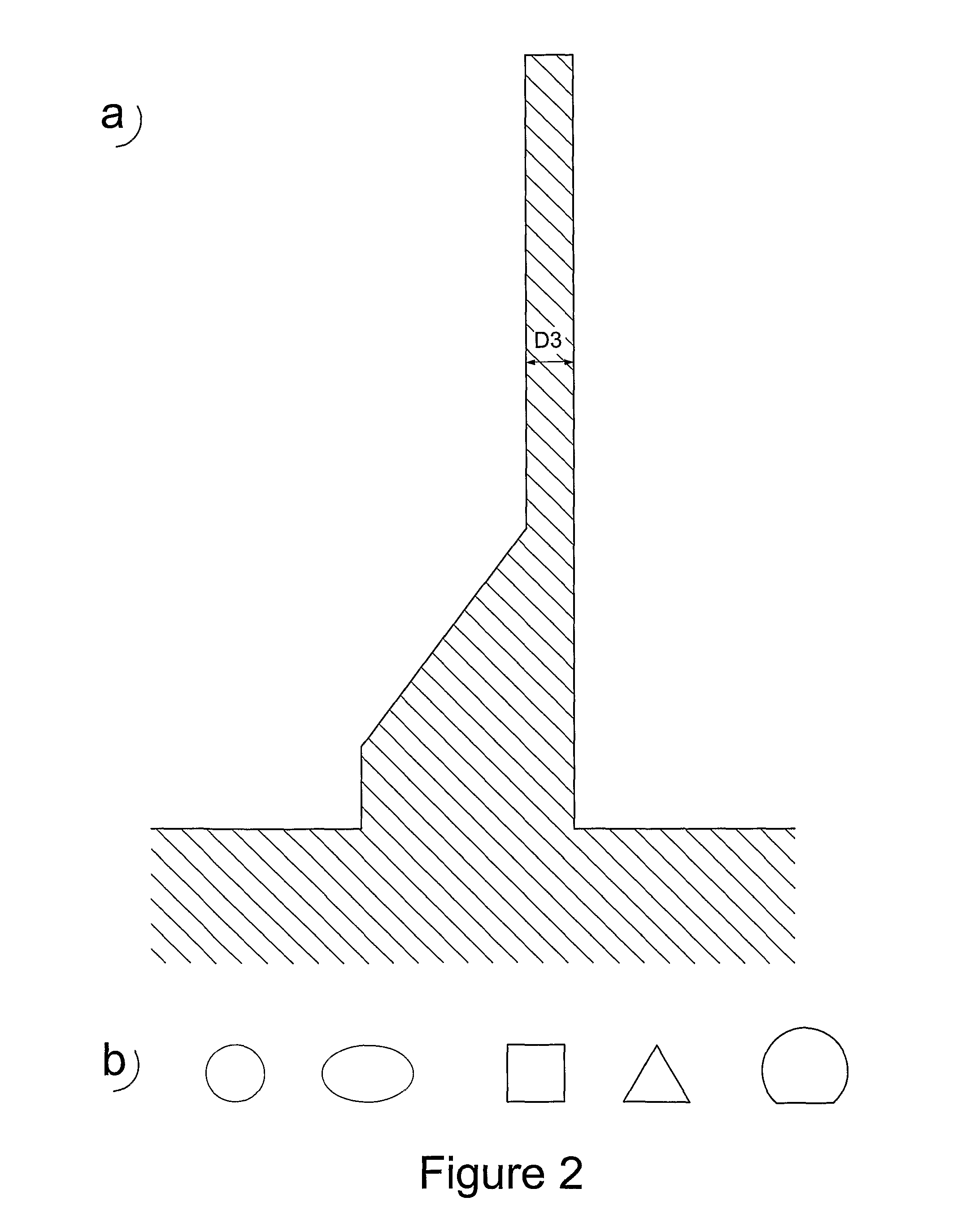
[0024] In a first embodiment, the method of making hollow micro-projections having side walls and at least one opening in a side wall, accordingly comprises providing an essentially cylindrical negative mold defining the exterior shape of said micro-projections. An essentially cylindrical positive mold defining the hollow interior shape of said micro-projections is also provided. The positive mold is brought into said negative mold, such that at least one portion of a side wall of said positive mold comes close enough to, and preferably in contact with, at least one portion of said negative mold to define an area corresponding to the desired side opening. A desired structure is molded by filling the space between said positive and negative mold with a moldable material. Finally, the desired structure is demolded from the molds. Any (molded) material that may be present within the area defining the side opening is removed so as to form said opening.

[0025] In other words, the step of ...

second embodiment

[0027] In a second embodiment the method comprises injecting a moldable material into the space between the two molds, in a state where they have been brought together. The positive and negative molds each have an essentially cylindrical geometry. In the process of bringing the molds together, the mold halves are laterally off-set with respect to each other, such that the distance between an inner wall of the negative mold and the positive mold in said area, ranges from zero to a finite distance. Said distance is smaller than the largest distance between the walls of the molds, thereby defining a side opening in an area of a side wall of said negative mold, so as to provide an opening or at least a thinner material thickness in said side wall area compared to the remaining side walls.

[0028] If necessary, a step of removing residual material from said area defining the side opening to open it up to create an opening is performed.

[0029] Suitably the structure is subjected to a harden...


PUM

PropertyMeasurementUnit
Structureaaaaaaaaaa
Moldableaaaaaaaaaa
Areaaaaaaaaaaa

Abstract

Method of hollow micro-projections having side walls and at least one opening in a side wall, by a molding technique. The hollow micro-projections are defined by a first, negative mold defining the exterior shape of the micro-projections and a second, positive mold defining the hollow interior shape of the micro-projections. The method includes injecting a moldable material into the space between the two molds, in a state where they have been brought together. The positive and negative molds each have an essentially cylindrical geometry. In the process of bringing the molds together, the mold halves are laterally off-set with respect to each other, such that the distance between an inner wall of the negative mold and the positive mold in the area, ranges from zero to a finite distance. Micro-projections and arrays of micro-projections are also disclosed.

Description

[0001] The present invention relates to a method of fabricating hollow micro projections comprising a sharp tip as well as at least one opening in the side surface of said projection. It also relates to the projections, in particular in the form of micro needles, suitable for a number of applications, such as micro injections of substances in the medical field. BACKGROUND OF THE INVENTION [0002] In applicants' own international patent application WO 03 / 015860 A1 (“Micro Needles and Method of Manufacture Thereof”) there is disclosed a method of manufacturing hollow micro-projections having side openings. Such projections are suitable for use as micro needles for e.g. injection through the skin of medicaments. [0003] The method disclosed in said WO publication is based on micro machining of e.g. silicon substrates. [0004] In an article by A. E. Guber et al (“Polymer Micro Needles With Through-going Capillaries”, in Micro Total Analysis Systems 2001, eds. Ramsey and van den Berg, pp 15...

Claims


Application Information

Patent Timeline
IPC IPC(8): A61M37/00A61K9/00A61M
CPCA61K9/0021A61M37/0015A61M2037/003A61M2037/0053B81C2201/034B29C2045/0094B81B2201/055B81B2203/0361B81C99/0085B29C45/2628
Inventor GRISS, PATRICKSTEMME, GORAN
Owner BONSENS
Why Eureka
Try Eureka