

Color display system with improved apparent resolution
a display system and apparent resolution technology, applied in the field of full-color display systems, can solve the problems of limited addressability of most flat-panel displays, limited apparent resolution of displays, and inability of human visual systems to resolve changes in physical resolution, so as to reduce image processing complexity and improve apparent resolution
Active Publication Date: 2007-11-08
GLOBAL OLED TECH
View PDF28 Cites 78 Cited by
- Summary
- Abstract
- Description
- Claims
- Application Information
AI Technical Summary
Benefits of technology
[0019] The advantages of this invention are a color display device with
Problems solved by technology
The first of these occur when the physical resolution of the display device is small enough that the human visual system is unable to resolve changes in physical resolution (i.e., the apparent resolution of the display becomes eye-limited).
Addressability in most flat-panel displays, especially active-matrix displays, is limited by the need to provide signal busses and electronic control elements in the display.
Depending upon the technology, reduction of the area of the light-emitting area can reduce the efficiency of light output, as is the case for LCDs, or reduce the brightness and/or lifetime of the display device, as is the case for EL displays.
Regardless of whether the area required for patterning busses and control elements competes with the light-emitting area of the display, the decrease in buss and control element size that occur with increases in addressability for a given display generally require more accurate, and therefore more complex, manufacturing processes and can result in greater number of defective panels, decreasing yield rate and increasing the cost of marketable displays.
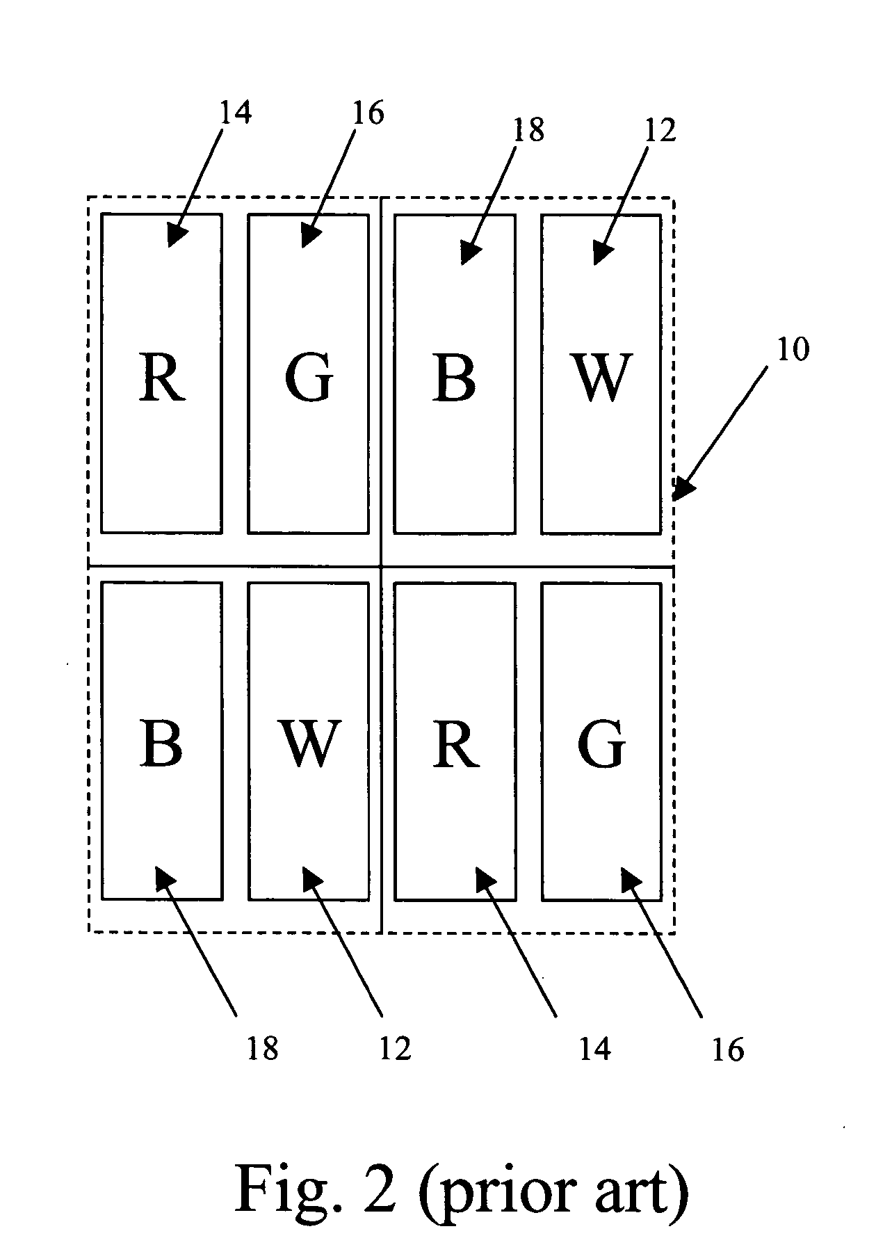
It is also recognized, however, that these effects can be quite image content dependent and therefore, displays that are designed to present text do not offset the position of light-emitting elements within alternate rows as this pixel arrangement creates the appearance of ragged edges on high contrast vertical lines, which occur frequently in text and this ragged appearance (commonly referred to as “jaggies”) can be quite disturbing to the user.
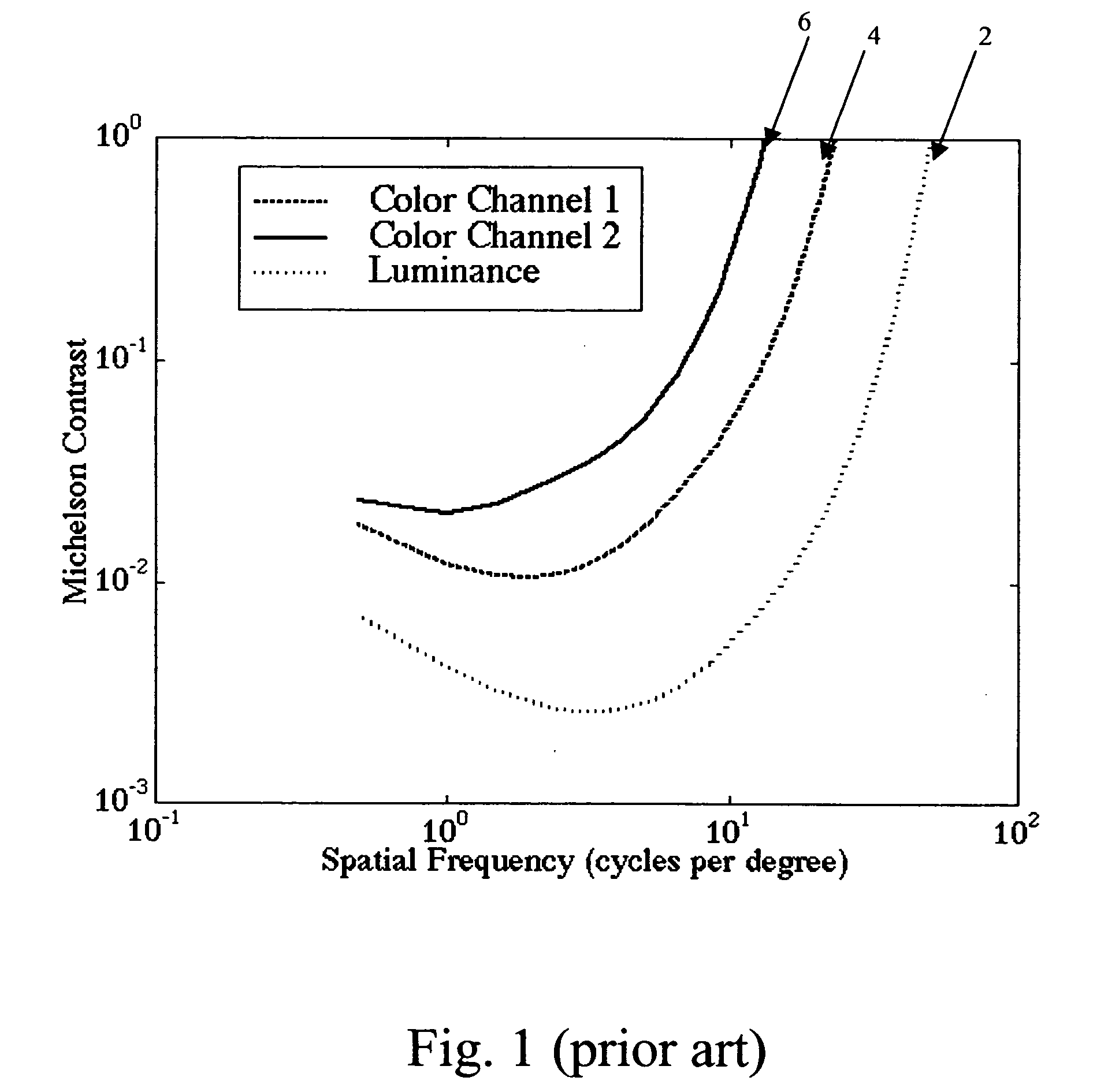
While subpixel interpolation methods known in the art allow different spatial filtering operations to be performed on signals that are intended for display on subpixels having different colors, they do not fully allow the optimization of the signal to take advantage of the difference in the human visual system's sensitivities to luminance and chrominance information.
To counter the blur introduced by such a subpixel interpolation algorithm, luminance bearing color channels must then be sharpened to boost the low frequency content in order to compensate for the lost high frequency content that occur
Method used
View moreImage
Smart ImageViewing Examples

Examples
 PUM
 Abstract
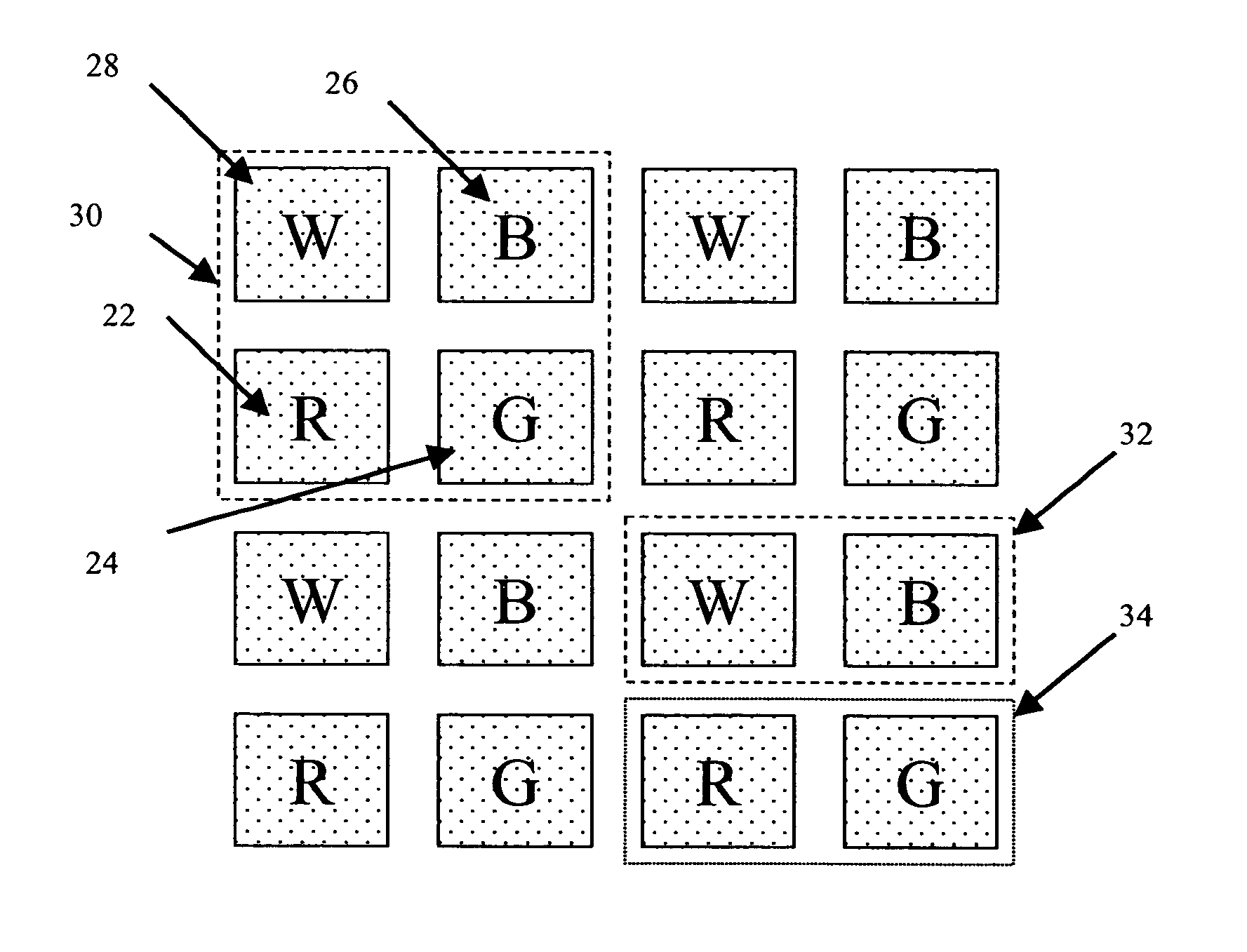
A full color display system comprised of: a) a display which is formed from a two-dimensional array of three or more differently colored light-emitting elements arranged in a repeating pattern forming a first number of full-color two-dimensional groups of light-emitting elements, each full-color group of light-emitting elements being formed by more than one luma-chroma sub-group of light-emitting elements, wherein the display has a peak white luminance and each luma-chroma sub-group comprising at least one distinct high-luminance light-emitting element having a peak output luminance value that is 40 percent or greater of the peak white luminance of the display device; and b) a processor for providing a signal to drive the display by receiving a three-or-more color input image signal, which specifies three-or-more color image values at each of a two-dimensional number of sampled addressable spatial locations within an image to be displayed; wherein the processor dynamically forms re-sampling functions for image spatial locations derived from the input image signal and corresponding to the spatial location of each luma-chroma sub-group in the display array based on an analysis of the spatial content of the three-or-more color input image signal and the display array repeating pattern, and applying the re-sampling functions to the three-or-more color input image signal to render a signal for driving each light-emitting element within each corresponding luma-chroma sub-group of light-emitting elements.
Description
FIELD OF THE INVENTION [0001] The present invention relates to full-color display systems and, more particularly, to arrangements of light-emitting elements in display devices of such color display systems and image processing for improving the apparent resolution of the display devices. BACKGROUND OF THE INVENTION [0002] Flat panel, color displays for displaying information, including images, text, and graphics are widely used. These displays may employ any number of known technologies, including liquid crystal light modulators, plasma emission, electro-luminescence (including organic light-emitting diodes), and field emission. Such displays include entertainment devices such as televisions, monitors for interacting with computers, and displays employed in hand-held electronic devices such as cell phones, game consoles, and personal digital assistants. In these displays, the resolution of the display is always a critical element in the performance and usefulness of the display. The...
Claims
Login to View More Application Information
Patent Timeline
 IPC IPC(8): G09G5/02
CPCG09G3/3225G09G2330/021G09G2300/0452
InventorMILLER, MICHAEL E.COK, RONALD S.
OwnerGLOBAL OLED TECH