Bullet-loading structure of toy gun

a toy gun and shell technology, applied in the field of shell-loading structure of toy guns, can solve the problems of reduced shooting performance, insufficient sucked gas, and reduced shooting performance, so as to improve the shooting performance of toy guns

Inactive Publication Date: 2007-11-15
ENLIGHT
View PDF4 Cites 39 Cited by
  • Summary
  • Abstract
  • Description
  • Claims
  • Application Information

AI Technical Summary

Benefits of technology

[0005] It is a main object of the present invention to provide a bullet-loading structure, wherein an actuation time of the pull rod is later than that of the piston to enable the piston to suck a lot amount of gas by using the maximum aperture of the bullet-pushing outlet, thereby preventing a gun tunnel from being blocked by the raised bullet and providing the simulated recoil effect, which simulates the real shooting, so as to improve the shooting performance of the toy gun.

Problems solved by technology

As a result, the gas suction is affected.
Besides, the sucked gas is more insufficient since the piston 40 is pushed back rapidly.
In addition, the centralization of the exhausted gas is also affected by the formation of the cross-shaped trench 801, resulting in the reduced shooting performance and the lack of recoil effect in real shooting.

Method used


Image

  • Bullet-loading structure of toy gun
  • Bullet-loading structure of toy gun
  • Bullet-loading structure of toy gun

Examples


Embodiment Construction

[0017] The above-mentioned features and advantages of this invention, and the manner of attaining them, will become more apparent and the invention will be better understood by reference to the following description of embodiments of the invention taken in conjunction with the drawings.

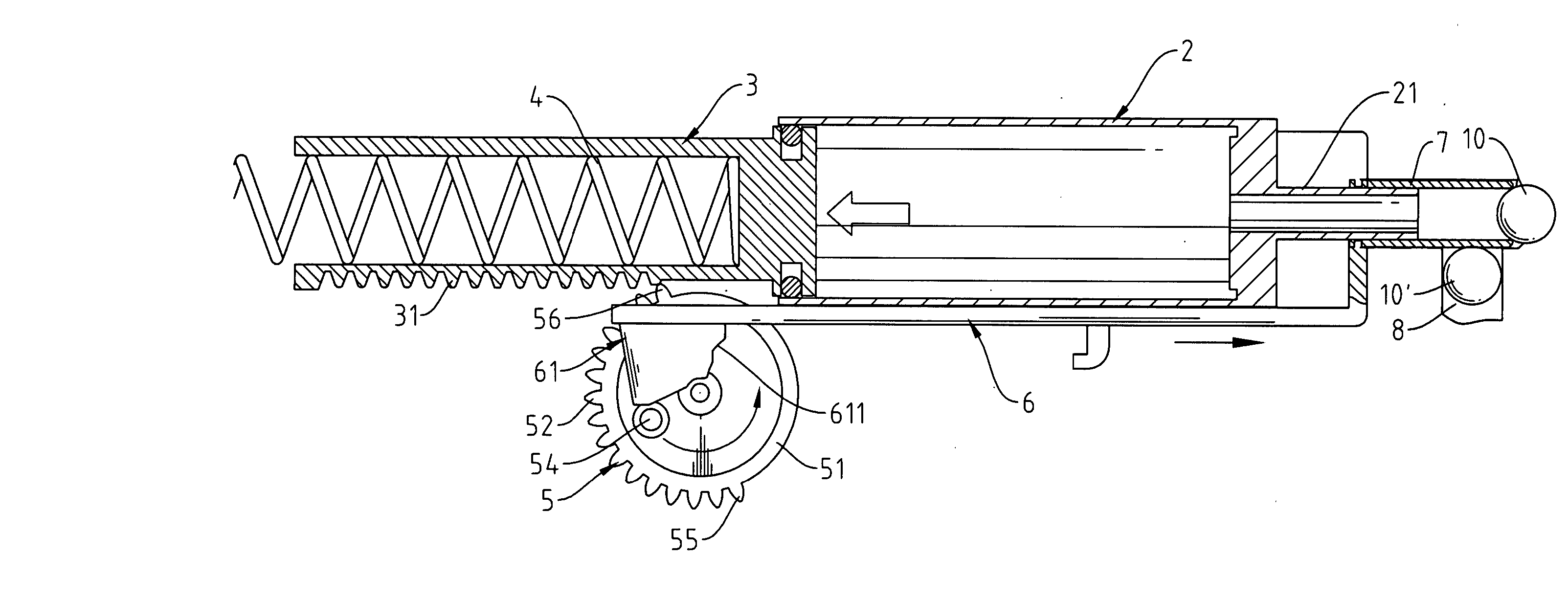
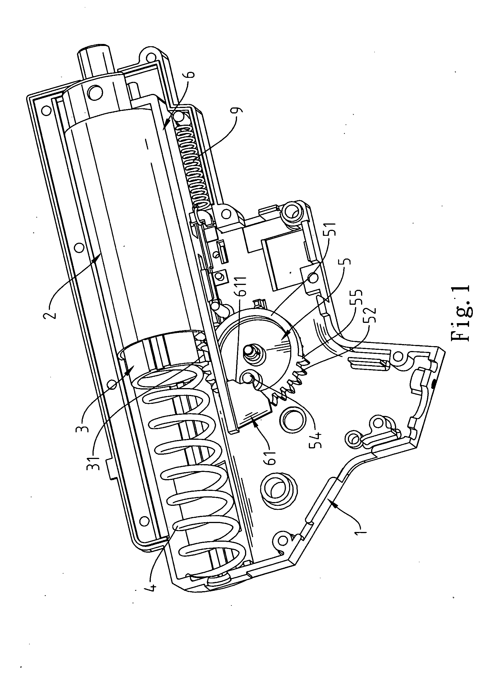
[0018] Referring to FIG. 1 and FIG. 2, a piston 3 is slidable in a cylinder 2 in a gun body 1 of the present invention and a compressible spring 4 is located between the piston 3 and a rear end of the gun body 1. The backward shifting of the piston 3 in the cylinder 2 causes the suction of the gas. Besides, the gas is compressed immediately when the piston 3 is shifted forward by the resilience force provided by the recovered compressible spring 4, which is compressed previously, such that the compressed gas is exhausted from a gas outlet 21 of the cylinder 2 for shooting a bullet.

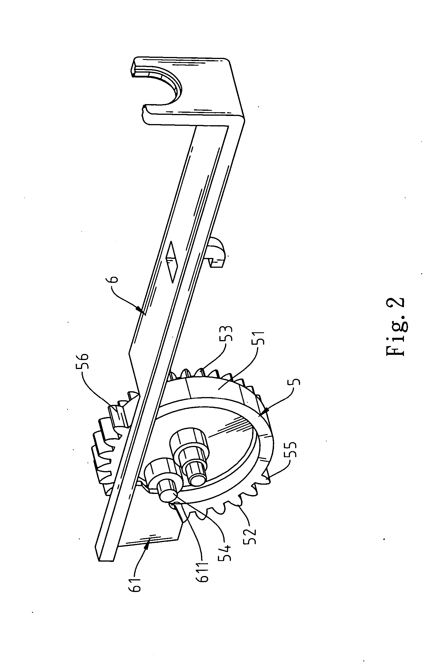
[0019] The power for shifting the piston 3 backward is supplied in accordance with the following description. A rack 31,...


PUM


Abstract

In a toy gun with a bullet-loading structure, a cylinder, a piston, a final gear, and a pull rod are mounted in a gun body. The piston and the pull rod are driven by the rotation of the final gear. An actuation time of the pull rod is later than that of the piston to enable the piston to suck a lot amount of gas before the loading of the bullet, thereby preventing a gun tunnel from being blocked by the raised bullet and providing the simulated recoil effect of real shooting so as to promote the shooting performance of the toy gun.

Description

FIELD OF THE INVENTION [0001] The present invention relates to a bullet-loading structure of a toy gun, and more particularly to a bullet-loading structure, wherein an actuation time of the pull rod is later than that of the piston so as to prevent a gun tunnel from being blocked by the raised bullet, thereby providing the simulated recoil effect, which simulates the real shooting, so as to promote the shooting performance of the toy gun. BACKGROUND OF THE INVENTION [0002] Referring to FIG. 9 through FIG. 11, wherein FIG. 9 and FIG. 10 are cross-sectional views showing the bullet-loading states of the conventional toy gun. This conventional toy gun utilizes a high torque motor to drive a final gear 20 for further driving a compressible spring 50 and a piston 40 having a rack 30. The compressible spring 50 is compressed when the piston 40 is shifted backward. At the same time, a certain amount of gas is sucked into a cylinder 60 for being compressed. When a tooth-shaped arc edge 201 ...

Claims


Application Information

Patent Timeline
Patent Type & Authority Applications(United States)
IPC IPC(8): F41B11/00
CPCF41B11/646
Inventor TAI, CHIAO-CHIHHUANG, SZU-MINGWANG, CHIA-CHENTIEN, CHIH-MING
Owner ENLIGHT
Why Eureka
Try Eureka