
Spray head structure of a spray gun

a spray gun and head structure technology, applied in the direction of spraying apparatus, spray nozzle, liquid spraying apparatus, etc., can solve problems affecting the performance of spraying operation

Inactive Publication Date: 2007-11-15
CHIA CHUNG PRECISION INDAL
View PDF21 Cites 36 Cited by
  • Summary
  • Abstract
  • Description
  • Claims
  • Application Information

AI Technical Summary

Benefits of technology

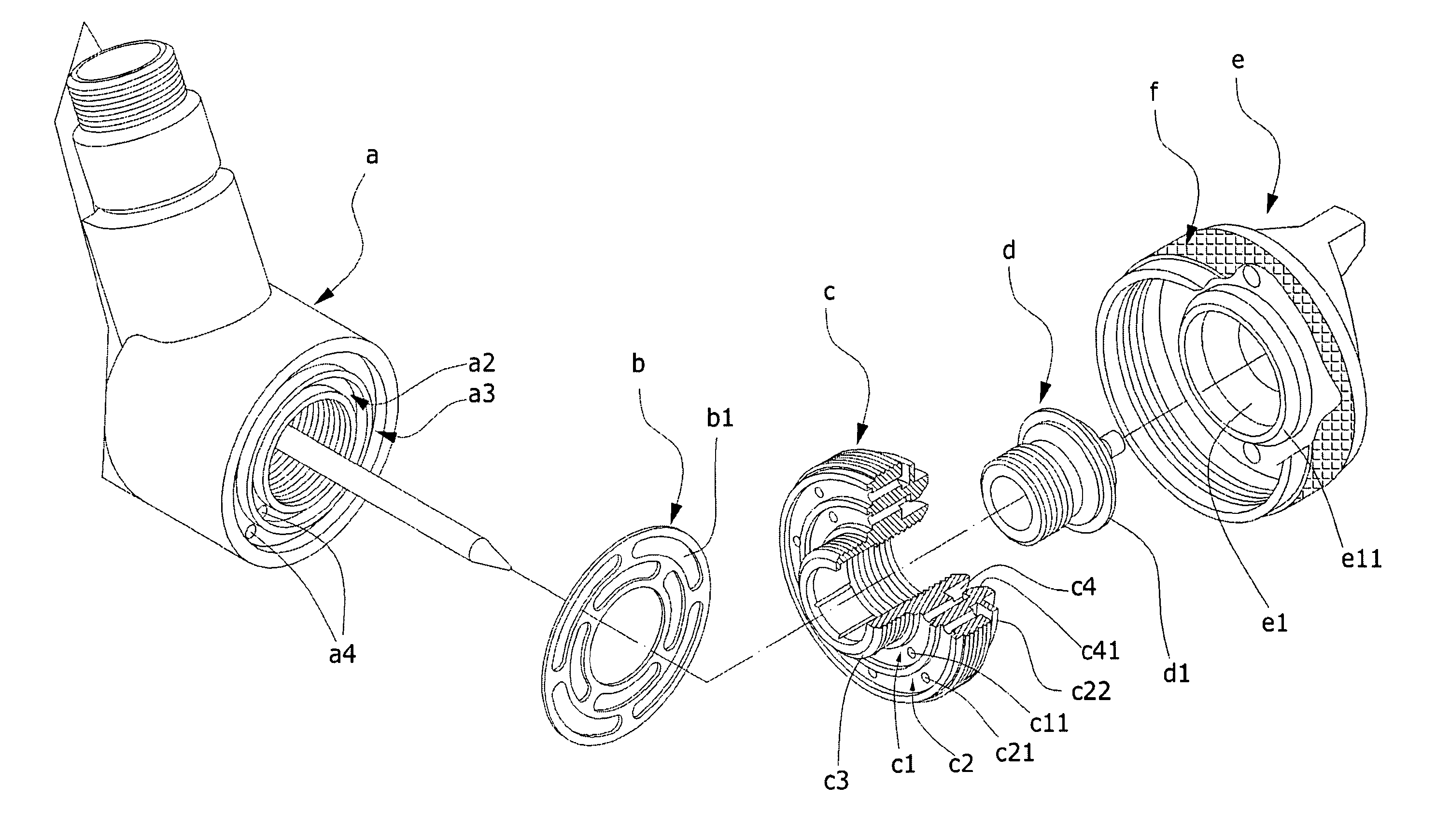
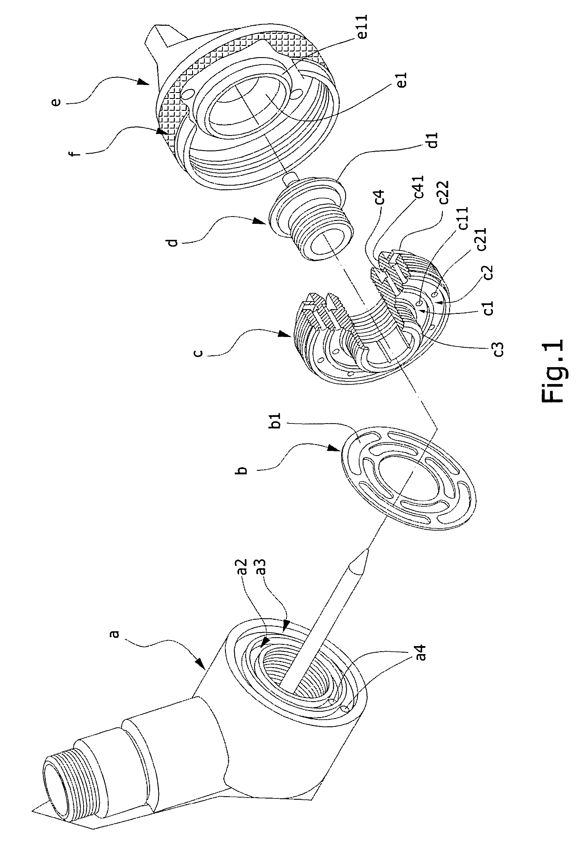
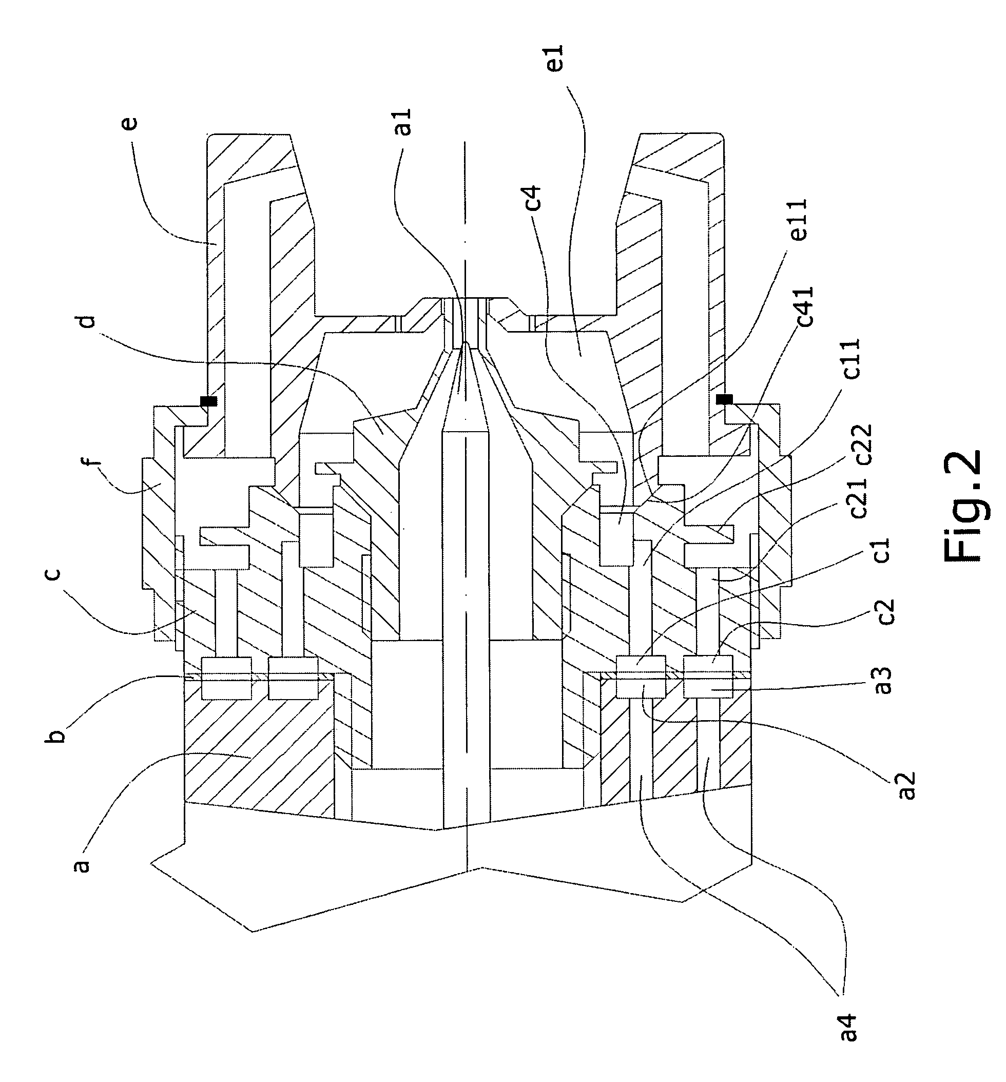
[0006] The primary object of present invention is to provide an improved structure of spray head which can uniformly shunt gas inside a spray gun to inner and outer ducts of spray head, and can also stabilize pressure of gas flowing in the inner and outer ducts.
[0008] According to the aforementioned structures, after the shunt sink is connected with the inner gas exit duct, and the outer gas hole is connected with the outer gas exit duct, the shunt sink can distribute equally the gas discharged from the inner gas exit duct into each gas hole of nozzle, and the gas discharged from the outer gas exit duct will flow through the outer gas hole and the connection hole of fixing seat to reach into the outer duct of cap, thereby achieving an effect of shunting the gas to the inner and outer ducts of spray head. By a pressure stabilizing structure formed by the cover ring of fixing seat and an outer wall of the screw tube of nozzle, and a pressure stabilizing structure formed by the flange ring of cap and an outer wall of a tip tube of nozzle, the pressure of gas flowing in the inner and outer ducts can be stabilized.

Problems solved by technology

In addition, in considering a requirement of a stable and uniform exit flow of gas, a pressure stabilizing structure is usually installed in a passage through which a high pressure gas will pass, in order to mitigate a direct escape of the high pressure gas from a nozzle during a process of discharging, thereby affecting a performance of spraying operation.
However, the aforementioned spray head structure is not provided with a shunt structure; therefore it is not suitable for a kind of spray gun which is only provided with a single inner, outer gas exit ducts, and wherein the inner, outer gas exit ducts are not installed with an inner, outer groove ring.

Method used


Image

  • Spray head structure of a spray gun
  • Spray head structure of a spray gun
  • Spray head structure of a spray gun

Examples


Embodiment Construction

[0015] Referring to FIG. 3 and FIG. 4, in a spray head structure of a spray gun of the present invention, a shunt ring 2, a fixing seat 3, a nozzle 4, a cap 5, and a screw nut 6 are orderly assembled at a front end of spray gun 1.

[0016] An adjusting pin 11 is extended from a center of front end part of the spray gun 1, and an inner wall of passage that the adjusting pin 11 passes through is provided with a thread part 12 for screwing with the fixing seat 3. An end surface on an exterior side of the passage is formed with a groove ring 13, and a proper position of end surface on the groove ring 13 is located with an inner gas exit duct 13a, an outer gas exit duct 13b, and two positioning holes 14 which are corresponding to positioning pillars 21 of the shunt ring 2.

[0017] Two end surfaces of the shunt ring 2 are extended outward with a plurality of positioning pillars 21 respectively, and proper positions on the end surface of shunt ring 2, facing to the spray gun 1, are separately...


PUM


Abstract

A spray head structure of a spray gun includes a shunt ring, and two end surfaces of which are extended outward with positioning pillars corresponding to position holes of a fixing seat and the spray gun, respectively. An end surface of the shunt ring, facing to the spray gun, is provided with a shunt sink and an outer gas hole, and the fixing seat is provided with a connection hole and a cover ring. Gas inside the spray gun can be shunted to an interior of spray head and pressure of the gas can be stabilized, by locking a nozzle with the shunt ring and the fixing seat.

Description

BACKGROUND OF THE INVENTION [0001] a) Field of the Invention [0002] The present invention relates to a spray head structure of a spray gun, and more particularly to a spray head structure wherein gas inside the spray gun is shunted without interfering with each other, and pressure of the gas after being shunted can be stabilized. [0003] b) Description of the Prior Art [0004] All of spray head products on the general market are designed to be more sophisticated to be in compliance with all kinds of various requirements. In addition, in considering a requirement of a stable and uniform exit flow of gas, a pressure stabilizing structure is usually installed in a passage through which a high pressure gas will pass, in order to mitigate a direct escape of the high pressure gas from a nozzle during a process of discharging, thereby affecting a performance of spraying operation. Referring to FIG. 1 and FIG. 2, in a Taiwan New Utility Patent 510253, “Spray Head Structure in which a Nozzle i...

Claims


Application Information

Patent Timeline
IPC IPC(8): B05B1/28B05B1/00
CPCB05B7/066B05B7/0861B05B7/0815
Inventor WANG, BEASON
Owner CHIA CHUNG PRECISION INDAL
Learn More