Method for mixing fluids in microfluidic channels

a microfluidic channel and fluid mixing technology, applied in clay preparation apparatus, transportation and packaging, chemistry apparatus and processes, etc., can solve the problems of inconvenient use of mixing axes, cumbersome channels, and difficult microfluidic mixing

Inactive Publication Date: 2007-11-15
TEXAS A&M UNIVERSITY
View PDF18 Cites 71 Cited by
  • Summary
  • Abstract
  • Description
  • Claims
  • Application Information

AI Technical Summary

Benefits of technology

[0013]In one embodiment of the invention, a fluid mixer is provided including one or more fluid inlet ports, a curved channel connected to the one or more fluid inlet ports including a first curved channel section and a second curved channel section disposed adjacent the first curved channel section, and an outlet port disposed adjacent the second curved channel section. In another embodiment of the invention, the second curved channel section comprises two or more sub-channels. In another embodiment of the invention, the second curved channel section has a width greater than the width of the first curved channel section.
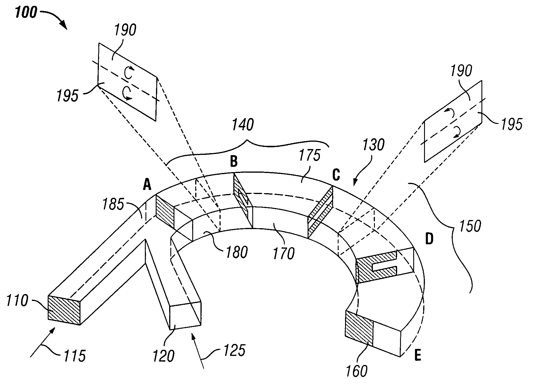
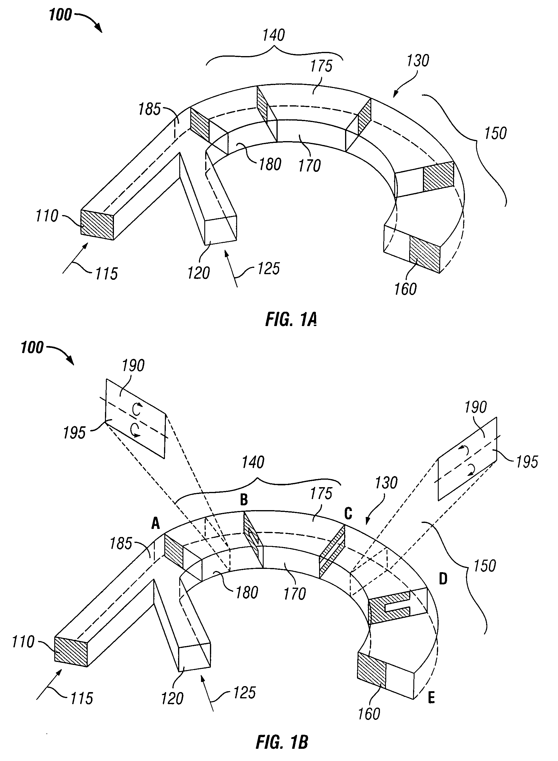
[0014]In another embodiment of the invention, a method is provided for mixing fluids in a channel, including providing a channel having a first curved channel section, and a second curved channel section, providing the two or more parallel fluid streams into the second curved channel section of the channel, mixing the two or more parallel fluid streams in the first curved channel section of the channel, and mixing the two or more parallel fluid streams in the second curved channel section of the channel. In another embodiment, the providing a first parallel fluid stream and a second parallel fluid stream to the channel by the one or more fluid inlet ports includes providing the first parallel fluid stream adjacent the inner channel wall and providing the second parallel fluid stream adjacent the outer channel wall. In another embodiment, mixing the two or more parallel fluid streams in the first curved channel section of the channel includes inducing at least a 90° rotation to the first parallel fluid stream and the second parallel fluid stream in the upper channel half of the first curved channel section and inducing at least a 90° counter rotation to the first parallel fluid stream and the second parallel fluid stream in the lower channel half of the first curved channel section. In another embodiment, mixing the two or more parallel fluid streams in the second curved channel section of the channel includes inducing at least a 90° rotation to the first parallel fluid stream and the second parallel fluid stream in the upper channel half of the second curved channel section and inducing at least a 90° counter rotation to the first parallel fluid stream and the second parallel fluid stream in the lower channel half of the second curved channel section.
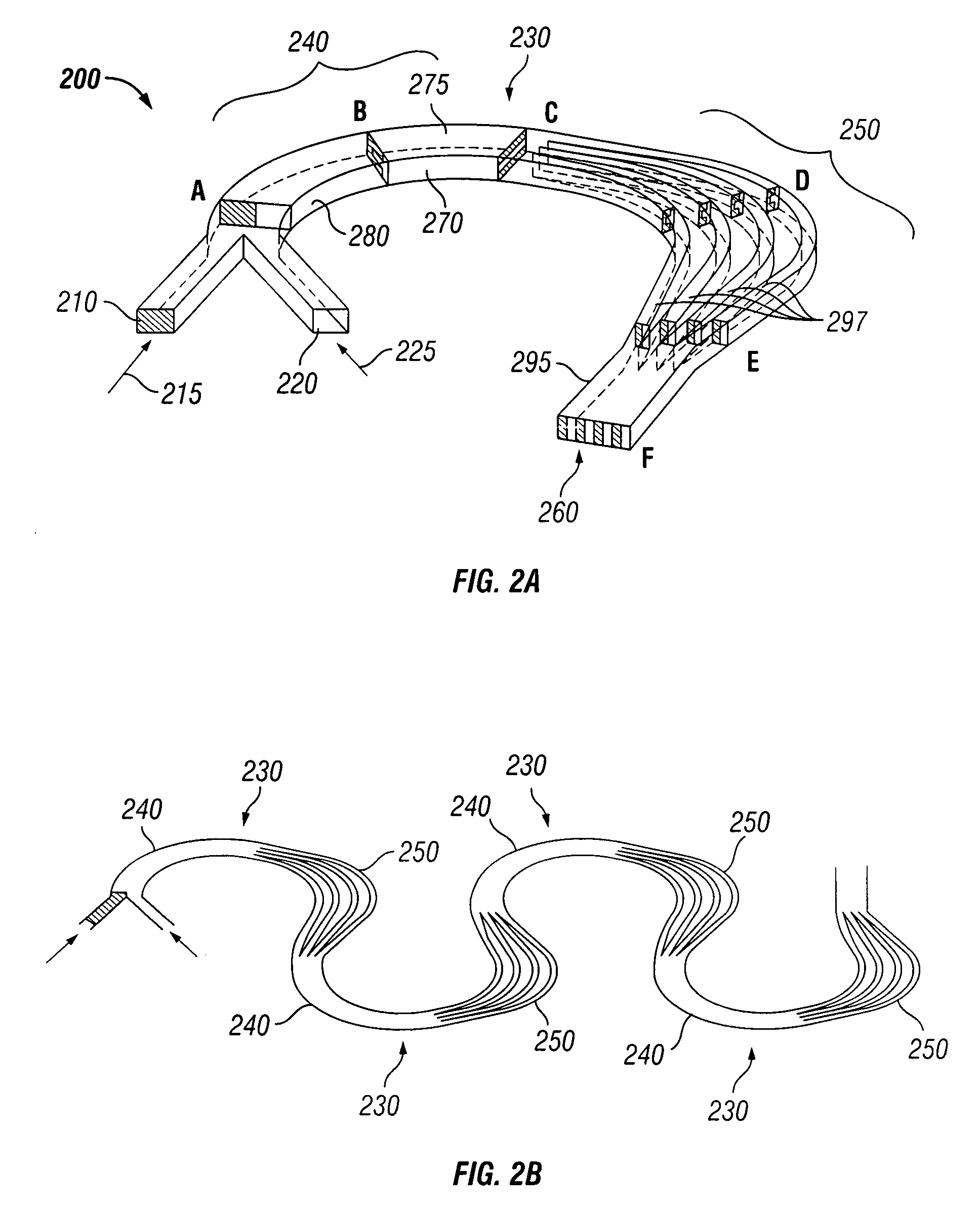
[0015]In another embodiment of the invention, mixing the two or more parallel fluid streams in the second curved channel section of the channel includes providing the two parallel fluid streams to the two or more sub-channels, inducing at least a 90° rotation to the first parallel fluid stream and the second parallel fluid stream in an upper channel half of each of the two or more sub-channels, inducing at least a 90° counter rotation to the first parallel fluid stream and the second parallel fluid stream in a lower channel half of each of the two or more sub-channels and recombining the two or more sub-channels into an outlet port.
[0016]In another embodiment of the invention, mixing the two or more parallel fluid streams in the second curved channel section of the channel includes providing the two parallel fluid streams to the second curved channel section, exposing the two parallel fluid streams to expansion vortices, inducing at least a 90° rotation to the first parallel fluid stream and the second parallel fluid stream in the upper channel half of the second curved channel section, and inducing at least a 90° counter rotation to the first parallel fluid stream and the second parallel fluid stream in the lower channel half of the second curved channel section.
[0017]In another embodiment of the invention, a fluid mixer is provided, including one or more fluid inlet ports, a channel section connected to the one or more fluid inlet ports, the channel section including, an inlet arc section connected to the one or more inlet ports, a transition section connected to the inlet arc section, an outlet arc section connected to the transition section, and an outlet port connected to the outlet arc section.

Problems solved by technology

However, microfluidic mixing is difficult to perform as the process is usually limited to an unfavorable laminar flow regime dominated by molecular diffusion and characterized by a combination of low Reynolds numbers (Re=Vd / v100, where D is the molecular diffusivity).
These factors combine to produce characteristic mixing lengths (Δym−V*(d2 / D)=Pe*d) on the order of several centimeters, resulting in the need to employ cumbersomely long channels in order to achieve complete mixing.
These mixing lengths axe generally prohibitively long and often negate many of the benefits of miniaturization.
While generally effective, these designs are often not easy to integrate with other microfluidic components and typically add substantial complexity to the fabrication process.
Moreover, since high electric fields, mechanical shearing, or generation of nontrivial amounts of heat are involved, they are not well suited for use with sensitive species (e.g., biological samples).
The microchannel structures associated with these mixing elements range from relatively simple topological features on one or more channel walls (ridges, grooves, or other protrusions that can, for example, be constructed by means of multiple soft lithography, alignment, and bonding steps) to intricate 3D (three dimensional) flow networks requiring timescales on the order hours to days to construct, often with expensive specialized equipment, and are generally impractical for mass production or routine use.
Additionally, attempts to provide mixing in 2D flow networks have not been successful as the corresponding Re in these experiments is fairly large (Re>>100) and outside the range of conditions that are realistically achievable in most microfluidic systems.
A variety of designs, such as variations of helical and “twisted pipe” arrangements have been investigated to enhance mixing in microfluidic systems; however, the corresponding nonplanar flow geometries often require multilevel or specialized fabrication processes that can introduce added complexity.
Conversely, the design of planar microchannels capable of sustaining transverse circulation over a sufficient downstream distance to compensate for the incompatibility between flow and diffusion timescales also has proven challenging.

Method used


Image

  • Method for mixing fluids in microfluidic channels
  • Method for mixing fluids in microfluidic channels
  • Method for mixing fluids in microfluidic channels

Examples


Embodiment Construction

[0026]The present invention relates to the formation of microfluidic mixers and processes for mixing fluids therein. In one embodiment of a fluid mixer, the fluid mixer includes one or more fluid inlet ports, a curved channel connected to the one or more fluid inlet ports, with the curved channel having a first curved channel section and a second curved channel section disposed adjacent the first curved channel section, and an outlet port disposed adjacent the second curved channel section. Multiple curved channels may be connected in sequence with the preferred configuration having each subsequent curved channel having a curvature opposition of the prior channel.

[0027]FIG. 1 is a schematic perspective view of one embodiment of the fluid mixer 100 comprising a first inlet port 110 and a second inlet port 120 for providing a respective first fluid 115, shown as shaded, and a respective second fluid 125 to a channel 130 having two or more curved sections, such as a first curved channe...


PUM

PropertyMeasurementUnit
Reynolds numberaaaaaaaaaa
heightaaaaaaaaaa

Abstract

Methods and apparatus are provided for mixing fluids. In one embodiment of the invention, a fluid mixer is provided including one or more fluid inlet ports, a curved channel connected to the one or more fluid inlet ports including a first curved channel section and a second curved channel section disposed adjacent the first curved channel section, and an outlet port disposed adjacent the second curved channel section. In another embodiment of the invention, a method is provided for mixing fluids in a channel, including providing a channel having a first curved channel section, and a second curved channel section, providing the two or more parallel fluid streams into the second curved channel section of the channel, mixing the two or more parallel fluid streams in the first curved channel section of the channel, and mixing the two or more parallel fluid streams in the second curved channel section of the channel.

Description

CROSS-REFERENCES TO RELATED APPLICATIONS[0001]This application claims benefit of U.S. Provisional Patent Application Ser. No. 60 / 799,537, filed on May 11, 2006, and U.S. Provisional Patent Application Ser. No. 60 / 835,032, filed on Aug. 2, 2006, each of which are incorporated herein by reference.STATEMENT REGARDING FEDERALLY SPONSORED RESEARCH OR DEVELOPMENT[0002]The patent application is supported by the National Institutes of Health under grant NIH k22-HG02297.REFERENCE TO A SEQUENTIAL LISTING[0003]None.BACKGROUND OF THE INVENTION[0004]1. Field of the Invention[0005]The present invention relates to fluid processing. In particular, the present invention relates to mixing fluids in channels.[0006]2. Background of the Art[0007]Microfluidics is becoming an increasingly important and mainstream technology in many chemical and biological process and analysis applications. The potential to replace large-scale conventional laboratory instrumentation with miniaturized and self-contained sys...

Claims


Application Information

Patent Timeline
Patent Type & Authority Applications(United States)
IPC IPC(8): B28C5/06
CPCB01F5/0644B01F5/0646B01F13/0059B01F5/0654B01F5/0647B01F25/4323B01F25/4331B01F25/4337B01F25/433B01F33/30
Inventor SUDARSAN, ARJUN P.UGAZ, VICTOR M.
Owner TEXAS A&M UNIVERSITY
Why Eureka
Try Eureka