Sound mask and sound box

Inactive Publication Date: 2007-11-15
ENSKY TECH CO LTD +1
View PDF19 Cites 13 Cited by
  • Summary
  • Abstract
  • Description
  • Claims
  • Application Information

AI Technical Summary

Benefits of technology

[0008]A sound mask is disclosed. The sound mask defines through holes. Rotational axis of the through holes are inclined relative to a surface normal of the sound mask. The sound mask is mounted in a sound box. The sound box includes at least one speakers corresponding to the through holes.

Problems solved by technology

But because of a limited space or short wires lengths of the sound boxes, the sound boxes may be unable to be positioned apart sufficiently, thus the sound effects are bad.
When the speakers are fitted in a same sound box, the speakers are adjacent to each other so that the sound effects are bad too.

Method used


Image

  • Sound mask and sound box
  • Sound mask and sound box
  • Sound mask and sound box

Examples


Embodiment Construction

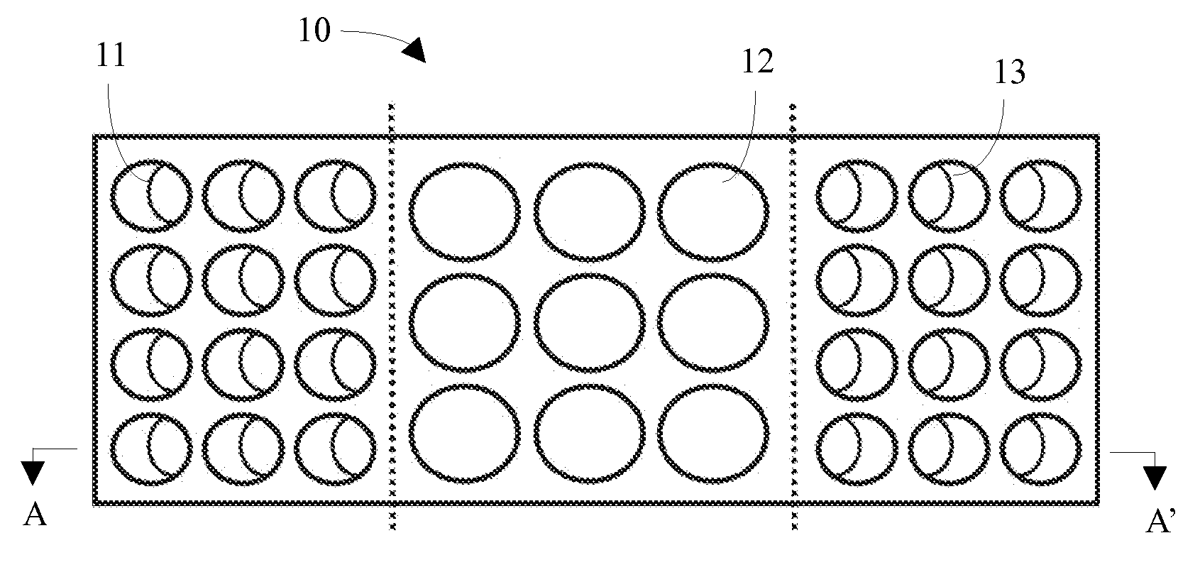
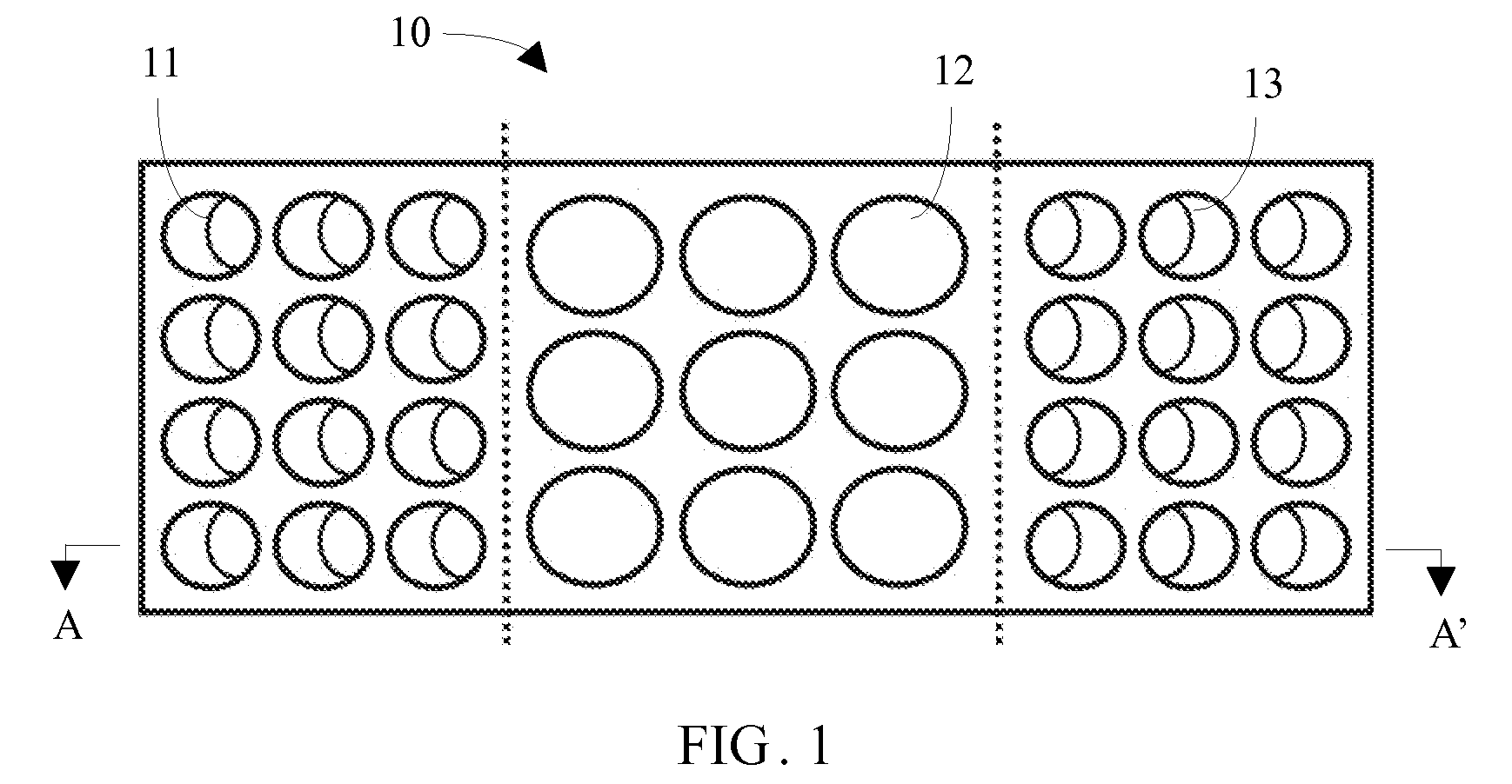
[0016]Referring to FIG. 1, a sound mask 10 is disclosed. A front surface of the sound mask 10 defines three sets of through holes 11, 12 and 13. The sets of through holes 11, 13 are inclined holes. The set of through holes 12 are straight holes. A center of axis of each of the straight holes 12 is parallel to a surface normal of the front surface.

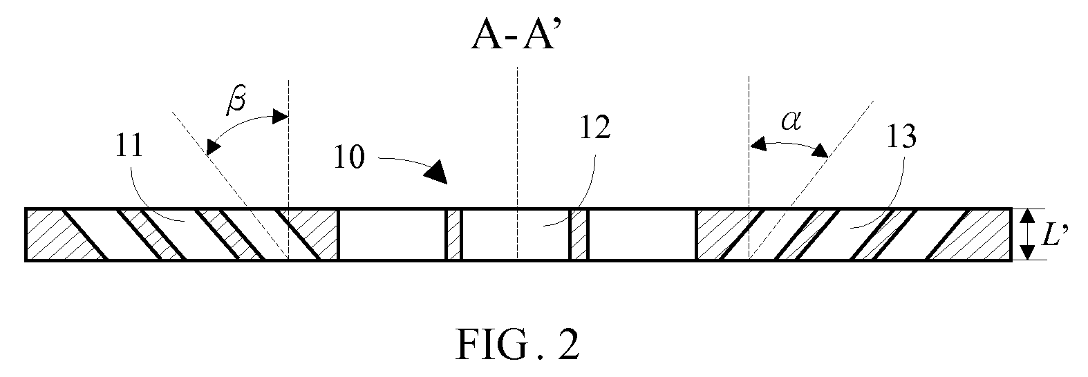
[0017]Referring to FIG. 2, a thickness of the sound mask 10 is denoted by L. A rotational axis of each of the through holes 13 is at a positive angle α relative to the surface normal of the sound mask 10. A rotational axis of each of the through holes 11 is at a negative angle β relative to the surface normal of the sound mask 10. An absolute value of the angle α is equal to that of the angle β.

[0018]Referring to FIG. 3, the sound mask 10 is mounted on a sound box 20. The sound box 20 includes speakers 21, 22, and 23. The speakers 21, 22, and 23 are configured under the through holes 11, 12, and 13 respectively. A distance between the speak...


PUM


Abstract

A sound mask is disclosed. The sound mask defines through holes. Rotational axis of the through holes are inclined relative to a surface normal of the sound mask. The sound mask is used in a sound box for obtaining a width sound field and a good distinguishing ability of sound source.

Description

BACKGROUND[0001]1. Technical Field[0002]The present invention relates to a sound mask and a sound box.[0003]2. General Background[0004]In multi-channel sound system, speakers are fitted in different sound boxes or in a same sound box.[0005]When the speakers are fitted in different sound boxes, the sound boxes should be positioned apart from each other so that sound sources can be distinguished and a wide width of sound field is obtained. But because of a limited space or short wires lengths of the sound boxes, the sound boxes may be unable to be positioned apart sufficiently, thus the sound effects are bad. When the speakers are fitted in a same sound box, the speakers are adjacent to each other so that the sound effects are bad too.[0006]Sound mask is equipped on the sound box for speaker protection and dust prevention, but isn't used for obtaining a width sound field and a good distinguishing ability of sound sources.[0007]Therefore, what is needed is a sound box having a width so...

Claims


Application Information

Patent Timeline
IPC IPC(8): H04R3/02
CPCH04R1/023H04R1/323H04R1/26
Inventor YU, TZU-CHENGYANG, TSUNG-LUNGHSIEH, KUAN-HONGLI, XIAO-GUANG
Owner ENSKY TECH CO LTD
Why Eureka
Try Eureka