Fuel pump

a fuel pump and pump body technology, applied in the direction of liquid fuel engines, liquid fuel feeders, machines/engines, etc., can solve the problems of insufficient reduction of fuel pressure, large amount of vapor formation, and difficulty in completely separating vapor and fuel, so as to reduce pump efficiency

Inactive Publication Date: 2007-11-15
AISAN IND CO LTD
View PDF6 Cites 8 Cited by
  • Summary
  • Abstract
  • Description
  • Claims
  • Application Information

AI Technical Summary

Benefits of technology

[0010]In this known fuel pump, by providing this narrow-diameter impeller for separating the vapor, any abrupt change in the pressure of the fuel can be reduced to a certain extent compared to the case where the fuel is drawn directly into a wide-diameter impeller. However, since the change in the pressure of the fuel is insufficiently reduced, a large amount of vapor may be formed. In this case, it is difficult to completely separate the vapor and the fuel, and consequently vapor remains within the fuel. The vapor remaining within the fuel may flow into a later stage of the impeller and cause a vapor lock. Pump efficiency thus is decreased.

Problems solved by technology

However, since the change in the pressure of the fuel is insufficiently reduced, a large amount of vapor may be formed.
In this case, it is difficult to completely separate the vapor and the fuel, and consequently vapor remains within the fuel.
The vapor remaining within the fuel may flow into a later stage of the impeller and cause a vapor lock.

Method used


Image

  • Fuel pump
  • Fuel pump
  • Fuel pump

Examples


embodiments

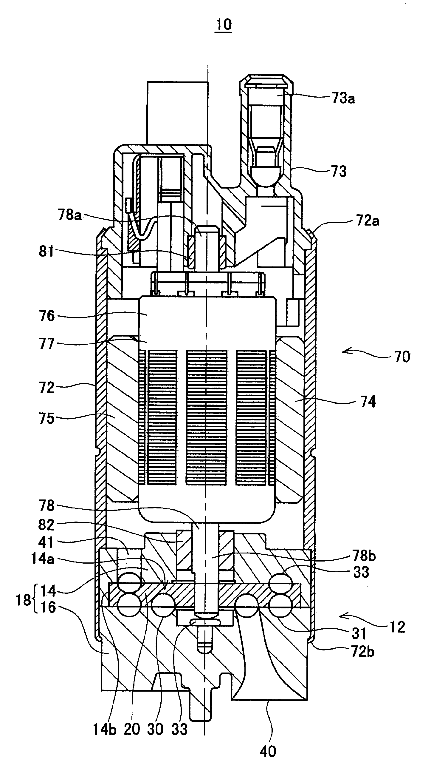
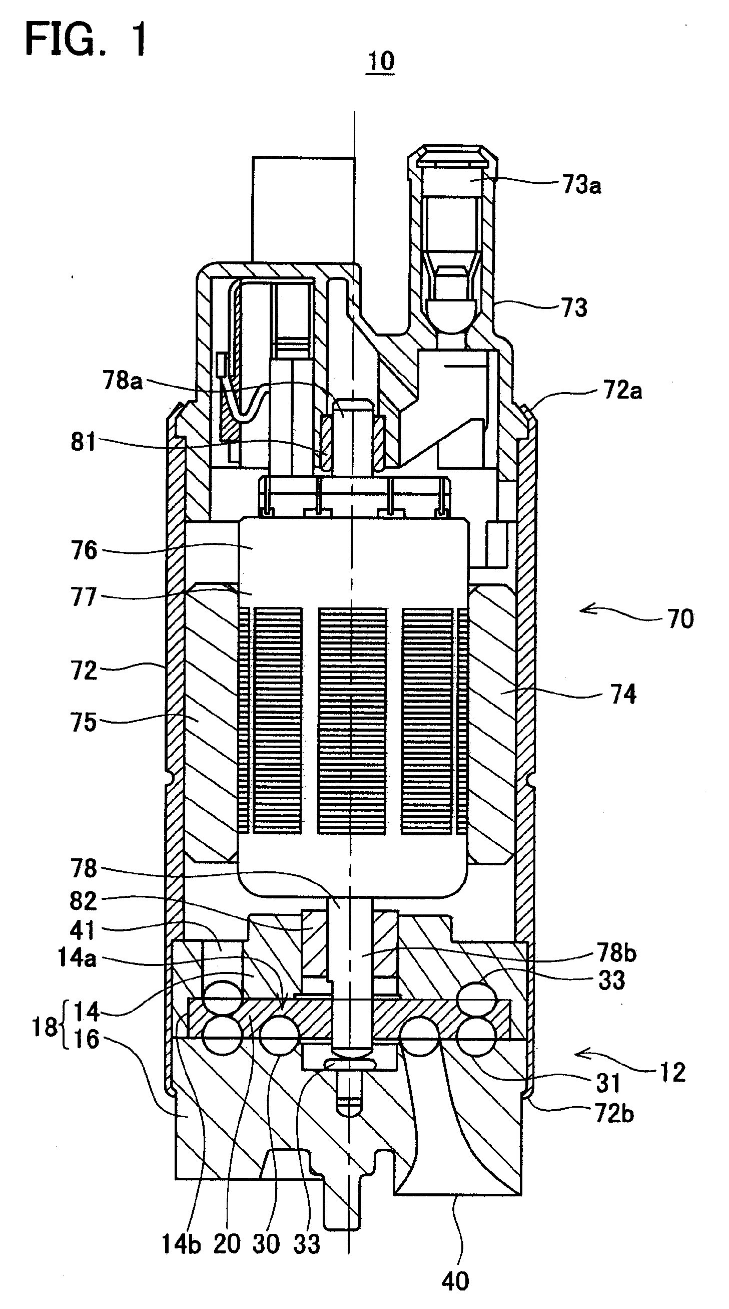
[0037]An embodiment according to the present teachings is described below with reference to figures. First, the mechanical configuration of a fuel pump will be described with reference to FIG. 1.

[0038]As shown in FIG. 1, the fuel pump 10 comprises a motor portion 70 and a pump portion 12.

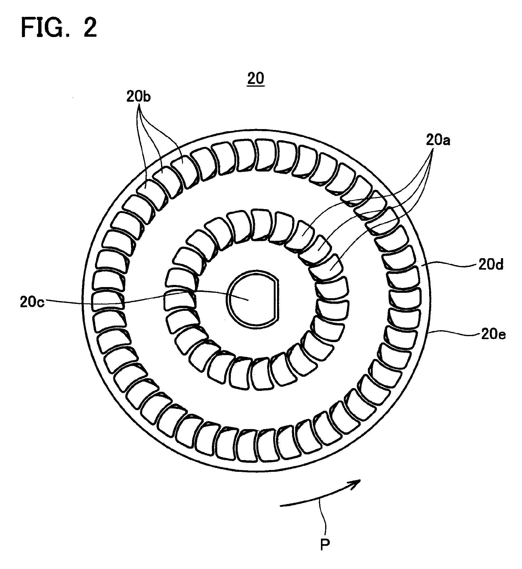
[0039]The motor portion 70 comprises a housing 72, a motor cover 73, magnets 74, 75, and a rotor 76. The housing 72 is formed in a substantially cylindrical shape. The motor cover 73 is attached to the housing 72 by caulking the upper end 72a of the housing 72 (hereafter, the up-down direction of FIG. 1 will be considered the up-down direction of the fuel pump 10). A discharge port 73a is formed in the motor cover 73. The magnets 74, 75 are fixed to the inner walls of the housing 72. The rotor 76 has a main body 77, and a shaft 78 that vertically extends through the main body 77. An upper end 78a of the shaft 78 is rotatably mounted on the motor cover 73 via a bearing 81. A lower end 78b of the shaf...


PUM


Abstract

A vapor lock in a fuel pump can be prevented by reducing the formation of vapor within the fuel. A first group of concavities may be formed in an inner circumferential region of an intake side face of an impeller, and a second group of concavities may be formed concentrically in a region outside of the first group of concavities. A third group of concavities that communicates with the second group of concavities may be formed in a discharge side face of the impeller. The impeller is housed within a casing. A first groove that faces the first group of concavities and a second groove that faces the second group of concavities may be formed in the face of the casing that faces the intake side face of the impeller. A third groove that faces the third group of concavities may be formed in the face of the casing that faces the discharge side face of the impeller.

Description

CROSS-REFERENCE TO RELATED APPLICATION[0001]This application claims priority to Japanese Patent Application No. 2006-130209 filed on May 9, 2006, the contents of which are hereby incorporated by reference into the present application.BACKGROUND OF THE INVENTION[0002]1. Field of the Invention[0003]The present invention relates to a fuel pump that comprises a casing and a substantially disc-shaped impeller rotating within the casing.[0004]2. Description of the Related Art[0005]Fuel pumps that functions as devices for supplying fuel within a fuel tank to an internal combustion engine (e.g., the engine of an automobile) are known to the art. This type of fuel pump usually comprises a motor portion and a pump portion. The pump portion comprises a casing and a substantially disc-shaped impeller housed so as to be capable of rotating within the casing. A first group of concavities is formed in a ring shape in the intake side face of the impeller. The first group of concavities is formed co...

Claims


Application Information

Patent Timeline
Patent Type & Authority Applications(United States)
IPC IPC(8): F04D5/00
CPCF02M37/048F04D29/445F04D5/006F04D5/005
Inventor YOSHIDA, SHIGERUMIURA, SATOSHI
Owner AISAN IND CO LTD
Why Eureka
Try Eureka