Pump for conveying a fluid

a technology for conveying fluids and pumps, applied in mechanical equipment, machines/engines, liquid fuel engines, etc., can solve problems such as deformation or even collapse of inserts, reduce the efficiency of pumps, and so as to reduce the risk of physical contact between impellers and stationary parts, the effect of reducing the gap and reducing the wear of the inserts

Active Publication Date: 2021-03-25
SULZER MANAGEMENT AG
View PDF0 Cites 2 Cited by
  • Summary
  • Abstract
  • Description
  • Claims
  • Application Information

AI Technical Summary

Benefits of technology

[0006]This gap is required to reduce the risk that the rotary part, i.e. the impeller, physically contacts the stationary part. In order to increase the operating safety and to reduce the wear the gap is usually configured with a safety margin, meaning that the width of the gap is configured such that the risk of a physical contact between the impeller and the stationary part is minimized. On the other hand, the larger the width of the gap is the larger is the backflow from the high pressure side to the low pressure side through the side room. A larger backflow, however, reduces the efficiency of the pump.
[0007]Nowadays in many applications the most efficient use of the pump is strived for. It is desirable to have the highest possible ratio of the power, especially the hydraulic power, delivered by the pump to the power needed for driving the pump. This desire is mainly based upon an increased awareness of environment protection and a responsible dealing with the available resources as well as on the increasing costs of energy.
[0008]An increase of the efficiency of the pump can be achieved by reducing the width of the gap so that the backflow is reduced. To this end, a stationary wear ring surrounding the shroud of the impeller with an insert having good friction properties, for example polyetheretherketone (PEEK), can be provided. By this measure it is possible to reduce the width of the gap, i.e. the clearance between the rotary part and the stationary part, by up to 50% without jeopardizing the operational safety of the pump. The PEEK insert considerably reduces the risk of galling during a possible contact between the rotary and the stationary part.
[0009]Although this measure has proven to be successfully in many applications, it has been found that problems arise with respect to the insert. The insert can deform or even collapse, i.e. the insert is not dimensionally stable. This results in an excessive wear in particular of the insert and can considerably reduce the efficiency of the pump.
[0010]It is therefore an object of the invention to propose a pump for conveying a fluid, having a high efficiency without an increased wear and without a reduction in the operating safety.

Problems solved by technology

A larger backflow, however, reduces the efficiency of the pump.
Although this measure has proven to be successfully in many applications, it has been found that problems arise with respect to the insert.
The insert can deform or even collapse, i.e. the insert is not dimensionally stable.
This results in an excessive wear in particular of the insert and can considerably reduce the efficiency of the pump.

Method used


Image

  • Pump for conveying a fluid
  • Pump for conveying a fluid
  • Pump for conveying a fluid

Examples


first embodiment

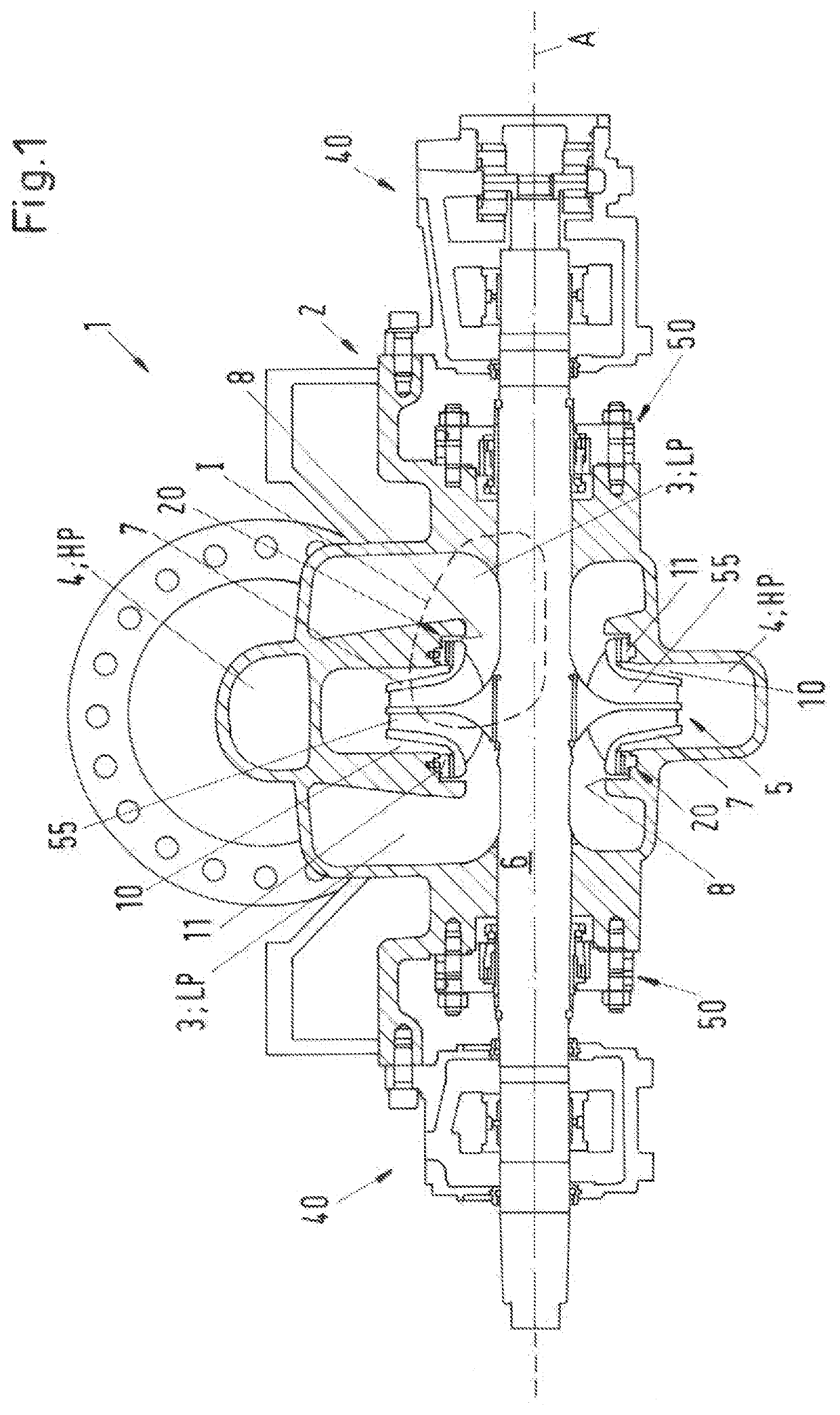
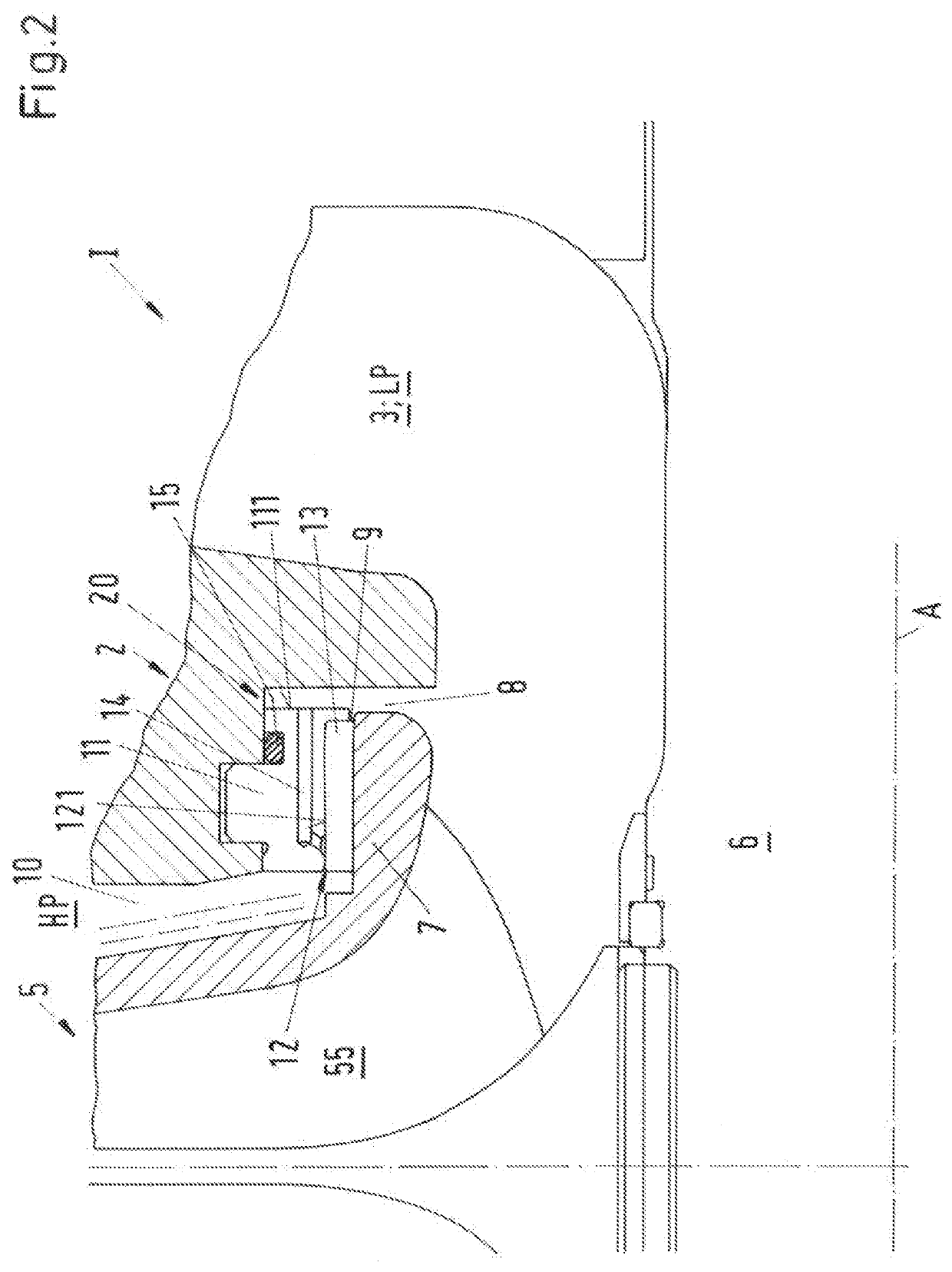
[0033]FIG. 1 shows a cross-sectional view of a pump according to the invention which is designated in its entity with reference numeral 1. FIG. 2 shows an enlarged representation of detail I in FIG. 1. The pump 1 is designed as a centrifugal pump for conveying a fluid, for example a liquid such as water.

[0034]In this first embodiment the pump 1 is designed as a double suction single stage centrifugal pump. This design is one of the preferred embodiments, which is in practice useful for many applications. Of course, the invention in not restricted to this design. A pump according to the invention can also be designed as a single suction centrifugal pump or as a multistage centrifugal pump or as any other type of centrifugal pump. Based upon the description of the embodiment shown in FIG. 1 and FIG. 2 it is no problem for the skilled person to build a pump according to the invention, that is designed as another type of pump, especially centrifugal pump, for example a single suction pu...

second embodiment

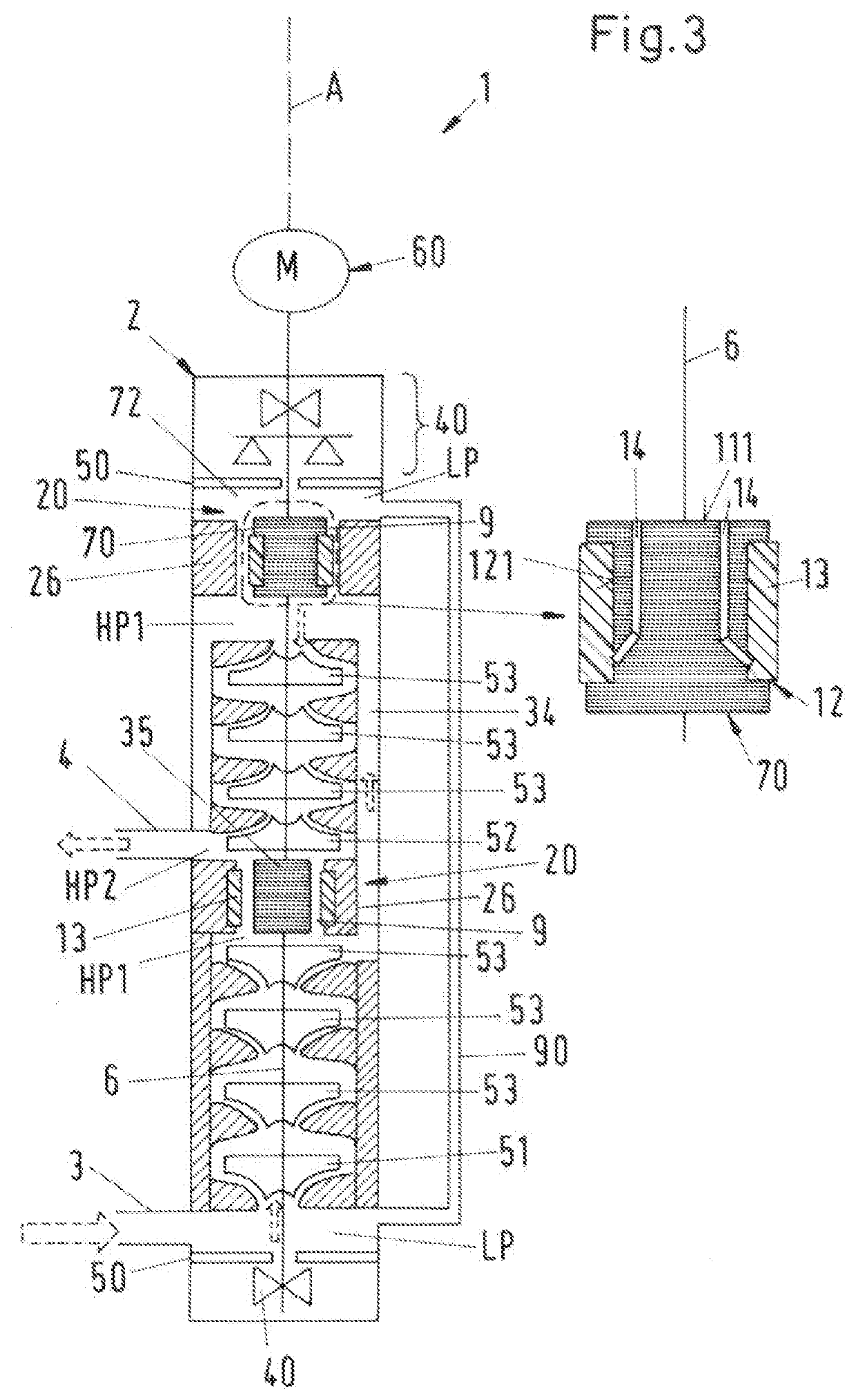
[0055]FIG. 3 shows a schematic cross-sectional view of a pump 1 according to the invention.

[0056]In the following description of the second embodiment of the pump 1 only the differences to the first embodiment are explained in more detail. The explanations with respect to the first embodiment are also valid in the same way or in analogously the same way for the second embodiment. Same reference numerals designate the same features that have been explained with reference to the first embodiment or functionally equivalent features.

[0057]The second embodiment of the pump according to the invention is configured as a multistage centrifugal pump 1. The shaft 6 is driven to rotate about the axial direction A by a drive unit 60, which comprises e.g. an electric motor. In other embodiments the drive unit 60 can also be arranged within the housing 2 of the pump 1.

[0058]The housing 2 of the pump 1 comprises only one inlet 3 through which the fluid enters the pump 1. Furthermore, the housing 2...


PUM


Abstract

A pump for conveying a fluid includes a stationary housing, an impeller conveying the fluid from a low pressure region to a high pressure region, a shaft to rotate the impeller about an axial direction, and a separation device to restrict a flow of the fluid from the high pressure region to the low pressure region. The separation device includes a rotary part connected to the shaft, and a stationary part stationary with respect to the housing. The rotary and stationary parts face each other and delimit a gap between the stationary part and the rotary part. The gap is arranged between the high and low pressure regions. A recess is disposed in the stationary part or the rotary part, the recess including a bottom, and a non-metallic insert is disposed in the recess. A relief channel enables fluid communication between the bottom and the low pressure region.

Description

CROSS-REFERENCE TO RELATED APPLICATION[0001]This application claims priority to European Patent Application No. 19199356.7, filed Sep. 24, 2019, the contents of which are hereby incorporated herein by reference in their entirety.BACKGROUNDField of the Invention[0002]The invention relates to a pump for conveying a fluid.Background Information[0003]Conventional pumps for conveying a fluid, for example a liquid such as water, are used in many different industries. Examples are the oil and gas industry, the power generation industry, the chemical industry, the water industry or the pulp and paper industry. Such pumps are often configured as centrifugal pumps having at least one impeller and a shaft for rotating the impeller. The at least one impeller may be configured for example as a radial impeller or as an axial or semi-axial impeller or as a helicoaxial impeller. Furthermore, the impeller may be configured as an open impeller or as a closed impeller, where a shroud is provided on th...

Claims


Application Information

Patent Timeline
Patent Type & Authority Applications(United States)
IPC IPC(8): F04D29/54F04D3/00F04D29/18F04D29/043
CPCF04D29/548F04D29/043F04D29/181F04D3/00F04D13/06F04D1/06F04D29/2222F04D29/669F04D29/026F04D29/0416F04D29/126F04D29/167F04D1/006
Inventor RADCLIFFE, CHRISTOPHER DAVIDJOHNE, TORSTENTISCHLER, HEIKEGIARDINO, FLAVIOWELSCHINGER, THOMAS
Owner SULZER MANAGEMENT AG
Why Eureka
Try Eureka