Centrifugal pump for conveying a fluid

a centrifugal pump and fluid technology, applied in the direction of non-positive displacement fluid engines, radial flow pumps, non-positive displacement pumps, etc., can solve the problems of reducing the hydraulic performance or reducing etc., to achieve the highest possible power ratio, reduce the efficiency of the pump, and increase the awareness of environmental protection

Inactive Publication Date: 2021-10-21
SULZER MANAGEMENT AG
View PDF0 Cites 1 Cited by
  • Summary
  • Abstract
  • Description
  • Claims
  • Application Information

AI Technical Summary

Benefits of technology

[0008]A sealing device such as a mechanical seal requires cooling for removing the heat from the sealing device, as well as flushing to keep particles away from the sealing elements. Therefore a certain flow is required for cooling and flushing. It is a known measure that the flow required to flush and to cool the sealing devices is extracted either at or near the outlet of the pump or at an intermediate stage of the pump. This required flow for flushing the sealing devices causes additional losses which reduces the efficiency of the pump.
[0009]Nowadays many applications strived for the most efficient use of the pump. It is desirable to have the highest possible ratio of the power, especially the hydraulic power, delivered by the pump to the power needed for driving the pump. This desire is mainly based upon an increased awareness of environment protection and a responsible dealing with the available resources as well as on the increasing costs of energy.
[0010]It is therefore an object of the invention to propose a centrifugal pump for conveying a fluid, having a high efficiency without a reduction in the operating safety of the pump.

Problems solved by technology

Of course, the leakage flow along the balance drum results in a decrease of the hydraulic performance or efficiency of the pump.
This required flow for flushing the sealing devices causes additional losses which reduces the efficiency of the pump.

Method used


Image

  • Centrifugal pump for conveying a fluid
  • Centrifugal pump for conveying a fluid

Examples


Embodiment Construction

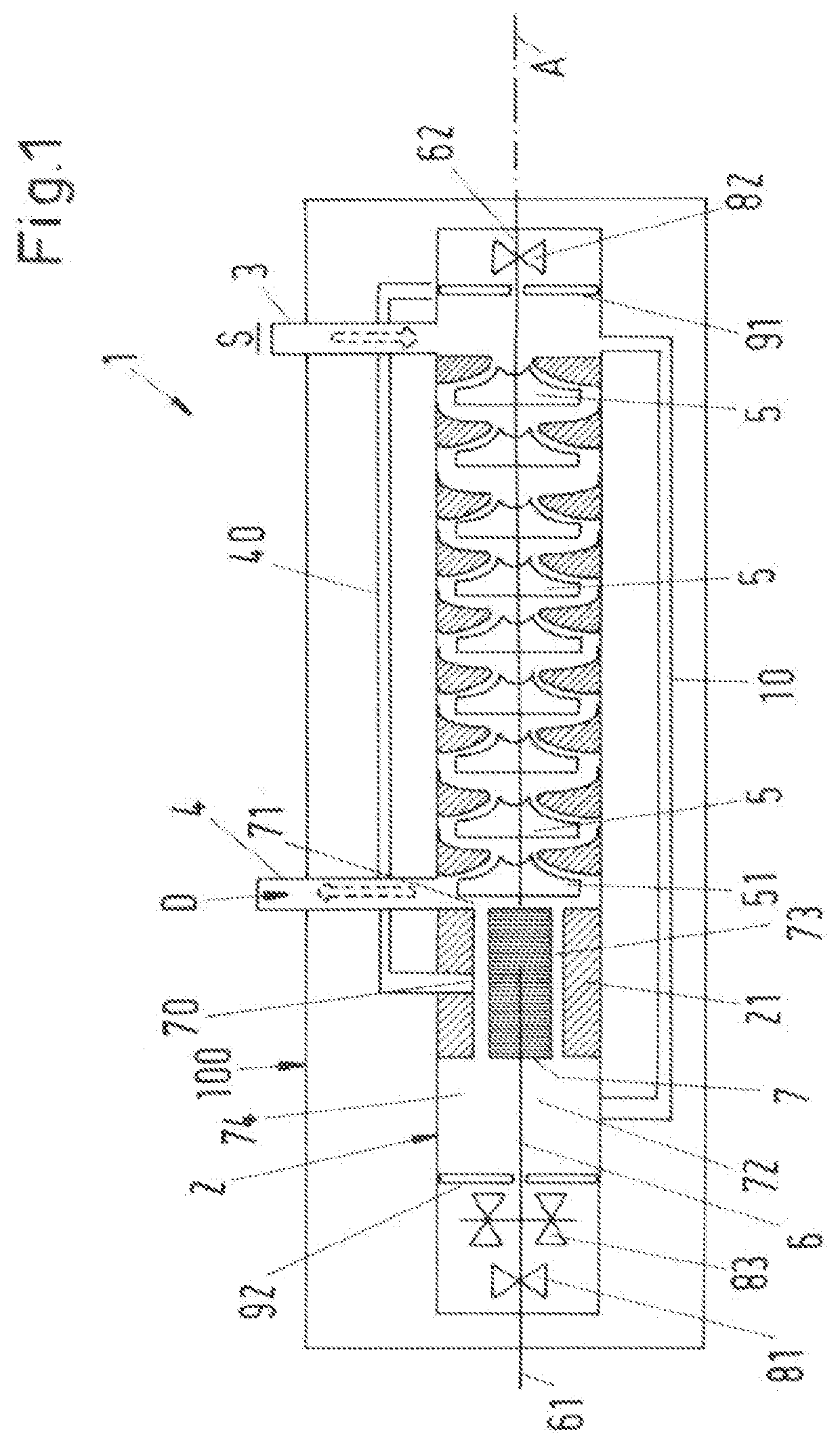
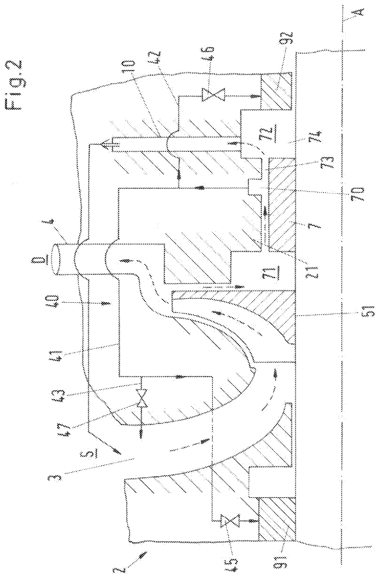
[0031]FIG. 1 shows a schematic cross-sectional view of an embodiment of a centrifugal pump according to the invention, which is designated in its entity with reference numeral 1. The pump 1 is designed as a centrifugal pump for conveying a fluid, for example a liquid such as water.

[0032]The centrifugal pump 1 comprises a pump housing 2 having an inlet 3 and an outlet 4 for the fluid to be conveyed. The inlet 3 is arranged at a suction side S, where a suction pressure prevails, and the outlet 4 is arranged at a discharge side D, where a discharge pressure prevails. The suction pressure is also referred to as low pressure, and the discharge pressure is also referred to as high pressure. The centrifugal pump 1 further comprises at least one impeller 5, 51 for conveying the fluid from the inlet 3 to the outlet 4 as indicated by the dashed arrows without reference numerals, as well as a shaft 6 for rotating each impeller 5, 51 about an axial direction A. The axial direction A is defined ...


PUM


Abstract

A centrifugal pump for conveying a fluid includes a pump housing, an impeller to convey the fluid from an inlet to an outlet, a shaft to rotate the impeller, a first sealing device to seal the shaft at a suction side, a second sealing device to seal the shaft at a discharge side, a balance drum connected to the shaft between the impeller and the second sealing device, the balance drum defining a front side facing the at least one impeller and a back side facing the second sealing device, a relief passage between the balance drum and a stationary part, a balance line connecting the back side with the suction side, a discharge opening arranged at the relief passage between the front side and the back side, and a connecting line connecting the discharge opening with the first sealing device.

Description

CROSS-REFERENCE TO RELATED APPLICATION[0001]This application claims priority to European Patent Application No. 20169858.6, filed Apr. 16, 2020, the contents of which are hereby incorporated herein by reference in their entirety.BACKGROUNDField of the Invention[0002]The invention relates to a centrifugal pump for conveying a fluid.Background Information[0003]Conventional centrifugal pumps for conveying a fluid, for example a liquid such as water, are used in many different industries. Some examples are the oil and gas industry, the power generation industry, the chemical industry, the water industry or the pulp and paper industry. Centrifugal pumps generally have at least one impeller and a shaft for rotating the impeller. The at least one impeller can be configured for example as a radial impeller or as an axial or semi-axial impeller or as a helicoaxial impeller. Furthermore, the impeller can be configured as an open impeller or as a closed impeller, where a shroud is provided on ...

Claims


Application Information

Patent Timeline
Patent Type & Authority Applications(United States)
IPC IPC(8): F04D15/00F04D1/06F04D29/22F04D29/10F04D29/043
CPCF04D15/0022F04D1/06F04D29/043F04D29/106F04D29/22F04D29/426F04D29/669F04D29/708F04D15/00F04D15/0005F04D29/0416F04D29/102
Inventor WIDMER, MARCRODRIGUES, ARNALDOCIMMINO, DANIELEWELSCHINGER, THOMAS
Owner SULZER MANAGEMENT AG
Why Eureka
Try Eureka