Coaxial seal for a pump

Inactive Publication Date: 2005-07-26
ENVIROTECH PUMPSYSTEMS INC
View PDF11 Cites 8 Cited by
  • Summary
  • Abstract
  • Description
  • Claims
  • Application Information

AI Technical Summary

Benefits of technology

[0009]The seal assembly of the present invention comprises two seal members which are coaxially aligned and radially oriented relative to each other, in contrast to known fluid pump seal mechanisms. That is, prior art seal mechanisms typically comprise several separate elements, one or more of which must be aligned and adjusted by a skilled workman, which introduces significant costs and time in assembling and servicing the pump. Prior art seal mechanisms also comprise seal members which are coaxial, but which are axially aligned in end-to-end or near adjacent arrangement to each other to produce an “in-line” orientation of the seal members. As such, in-line seal members make the sealing mechanism greater in length and result in a longer fluid inlet. Undesired increases in the available net pump suction head (NPSH) of the pump may result, which can reduce the efficiency of the pump.
[0010]The coaxial and radial orientation of the seal members of the present invention provides a simplified sealing assembly which does not require skilled manpower to install or align, and enables simple and relatively quick maintenance of the pump when the seal assembly requires repair or replacement. Moreover, because the seal members of the present invention are radially oriented, the axial length of the seal assembly is shorter than known seal assemblies and the fluid inlet may be correspondingly shorter. Improvements in pump efficiency may be observed.
[0011]The shorter axial length of the seal assembly of the present invention also enables the overall length of the pump to be shorter. Therefore, the cost of manufacturing the pump is less due to less materials and fewer components being required for construction of the pump, and the pump can be used in a greater variety of pumping applications than known larger pumps. These and other advantages of the present invention will become more apparent with consideration of the detailed description which follows.

Problems solved by technology

That is, prior art seal mechanisms typically comprise several separate elements, one or more of which must be aligned and adjusted by a skilled workman, which introduces significant costs and time in assembling and servicing the pump.
As such, in-line seal members make the sealing mechanism greater in length and result in a longer fluid inlet.
Undesired increases in the available net pump suction head (NPSH) of the pump may result, which can reduce the efficiency of the pump.

Method used


Image

  • Coaxial seal for a pump
  • Coaxial seal for a pump
  • Coaxial seal for a pump

Examples


Embodiment Construction

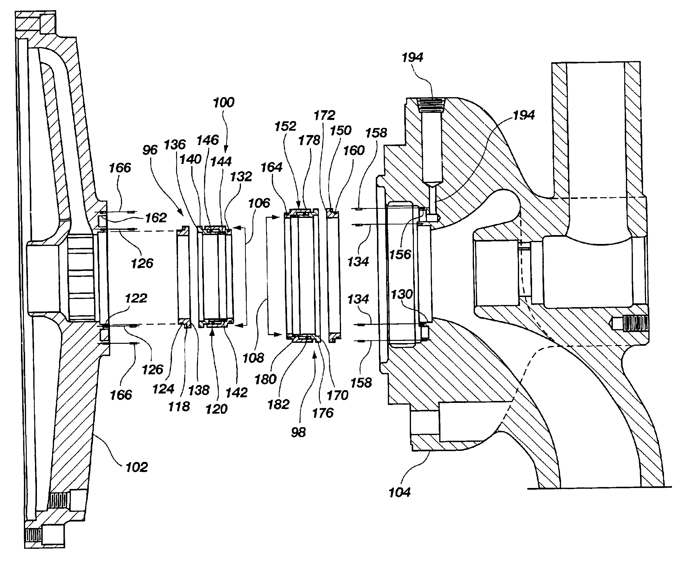
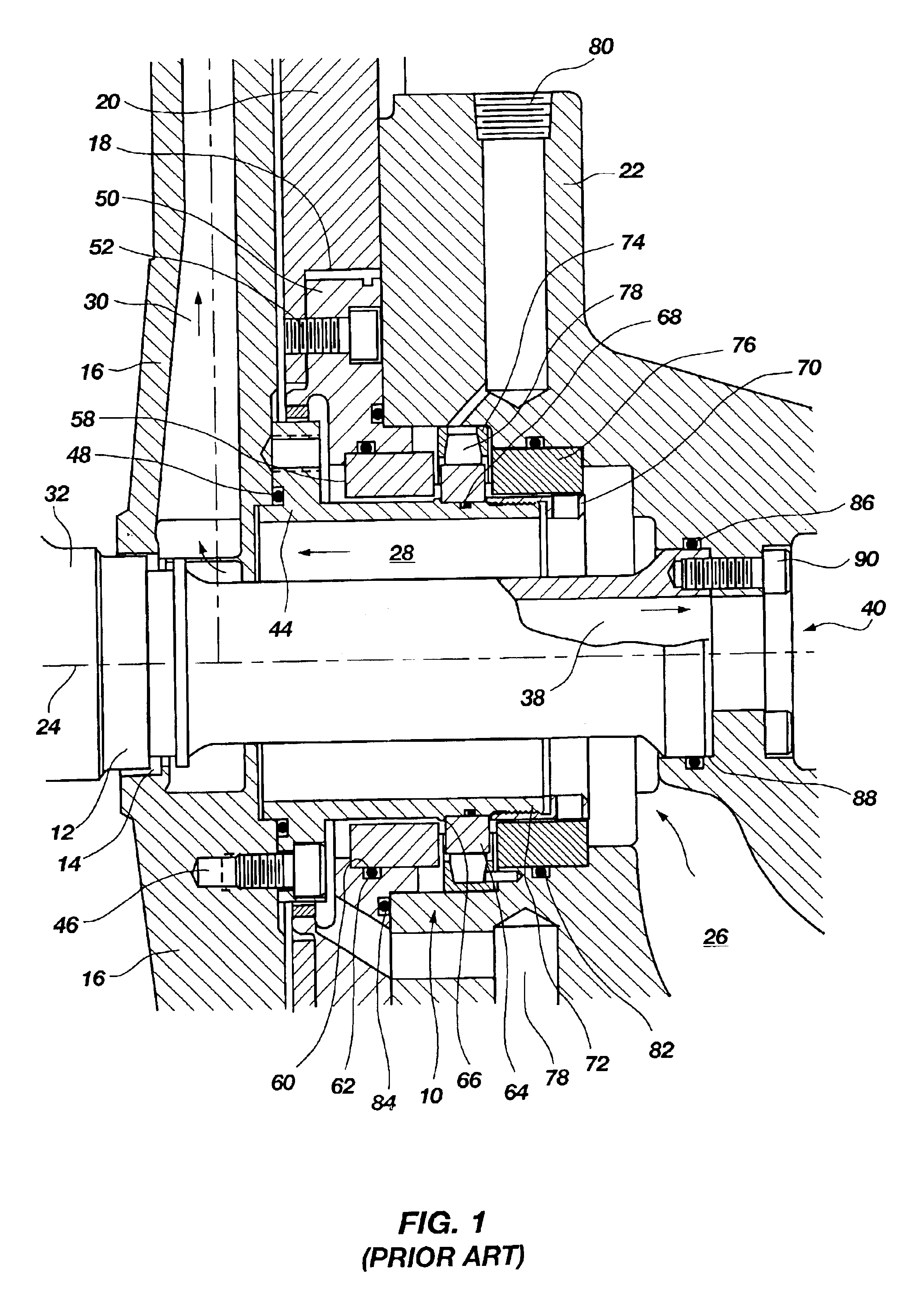
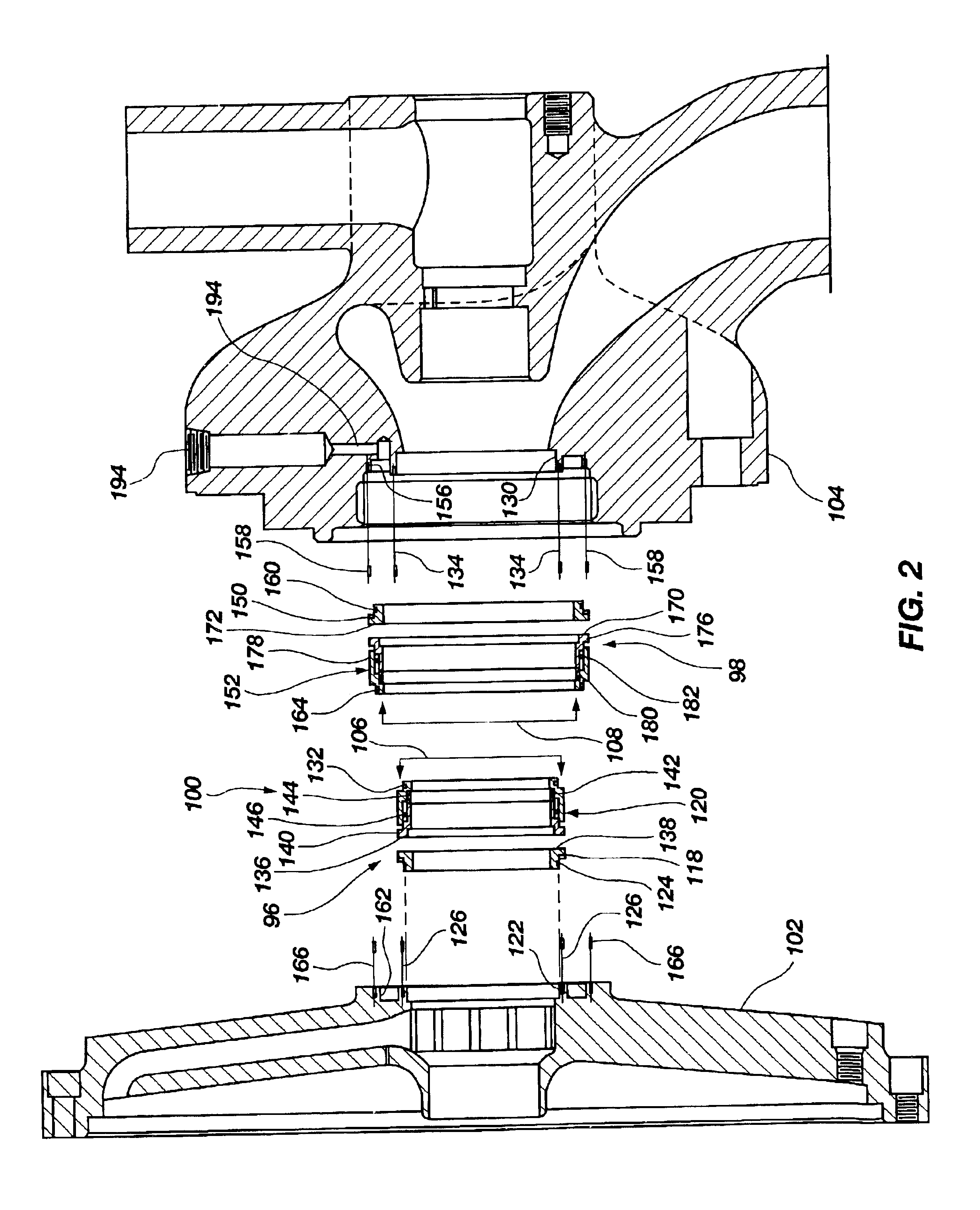
[0016]FIG. 1 illustrates a portion of a centrifugal pump of the pitot tube type which is known in the prior art. The basic elements of a centrifugal pump of the pitot tube type are well-known in the art as exemplified by, for example, U.S. Pat. No. 4,280,790, the contents of which are incorporated herein by reference. Although details of pitot tube pump structure are not illustrated herein because they are well known in the art, it is nonetheless instructive to the understanding of the present invention to note that pitot tube pumps generally comprise a pump casing that houses a rotating casing, or rotor, through which is positioned a stationary pitot tube assembly having a pitot tube arm. In operation, fluid enters into a fluid inlet formed in the pump casing and around the pitot tube assembly, and then enters into the rotor. The fluid is spun to the periphery of the rotor where it encounters an inlet opening in the pitot tube and flows from the inlet of the pitot tube through the ...


PUM


Abstract

A sealing mechanism for a fluid pump comprises first and second seal members which are coaxially and radially oriented relative to each other, and are positioned between the rotating and non-rotating elements of the fluid pump to maintain a competent seal which is simple to assembly, maintain and repair or replace, and which also improves pump operation when compared to known sealing mechanisms for fluid pumps.

Description

BACKGROUND OF THE INVENTION[0001]1. Field of the Invention[0002]This invention relates to sealing systems for industrial pumps and specifically relates to a simplified coaxial seal system for rotary fluid pumps.[0003]2. Description of the Related Art[0004]Rotary fluid pumps generally comprise a rotating element, such as an impeller or a rotor, housed within a stationary pump casing. Sealing means are provided between the rotating element and stationary elements of the pump to prevent fluid from infiltrating between the rotating and stationary elements. The type and configuration of sealing means varies widely between types and manufacture of fluid pumps. While it has been known to employ gas as a means of providing a “sealless” sealing systems, most liquid pumps employ mechanical seals.[0005]Sealing assemblies or mechanisms of industrial fluid pumps comprise a sealing element which rotates with the rotating element of the pump and another sealing element which is associated with the...

Claims


Application Information

Patent Timeline
IPC IPC(8): F04D29/08F04D29/12F16J15/34
CPCF04D29/126F16J15/3404F16J15/3484
Inventor QUINN, JOEL
Owner ENVIROTECH PUMPSYSTEMS INC
Why Eureka
Try Eureka