Diagnostics in process control and monitoring systems

a monitoring system and process control technology, applied in the direction of program control, fluid tightness measurement, electric unknown time interval measurement, etc., can solve the problem that the various components used in the industrial process, or to control or monitor the industrial process, tend to degrade through continued us

Active Publication Date: 2007-11-22
MICRO MOTION INC
View PDF65 Cites 17 Cited by
  • Summary
  • Abstract
  • Description
  • Claims
  • Application Information

AI Technical Summary

Problems solved by technology

During operation of industrial processes, the various components used in the industrial process, or to control or monitor the industrial process, tend to degrade through continued use.

Method used


Image

  • Diagnostics in process control and monitoring systems
  • Diagnostics in process control and monitoring systems
  • Diagnostics in process control and monitoring systems

Examples


Embodiment Construction

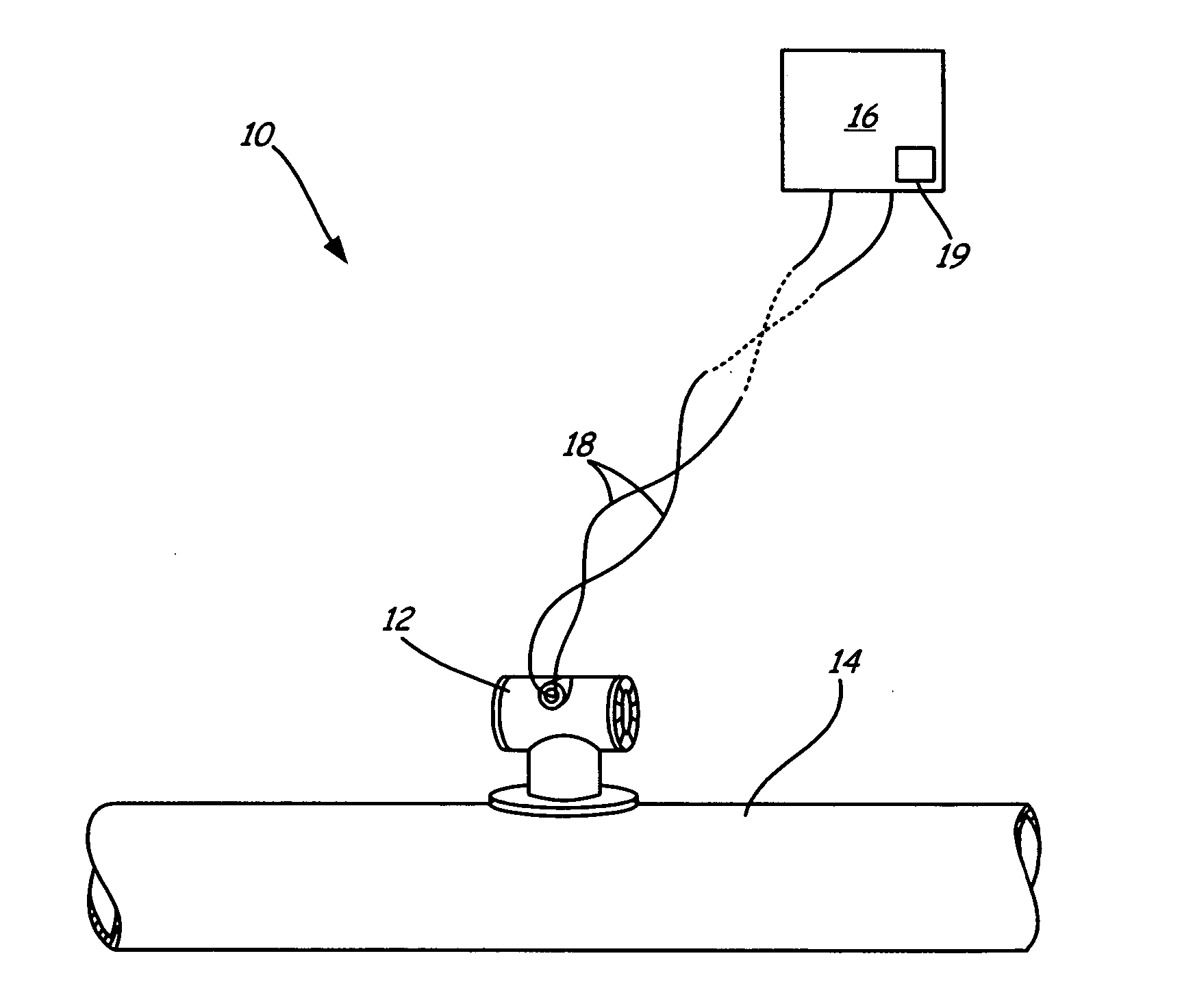
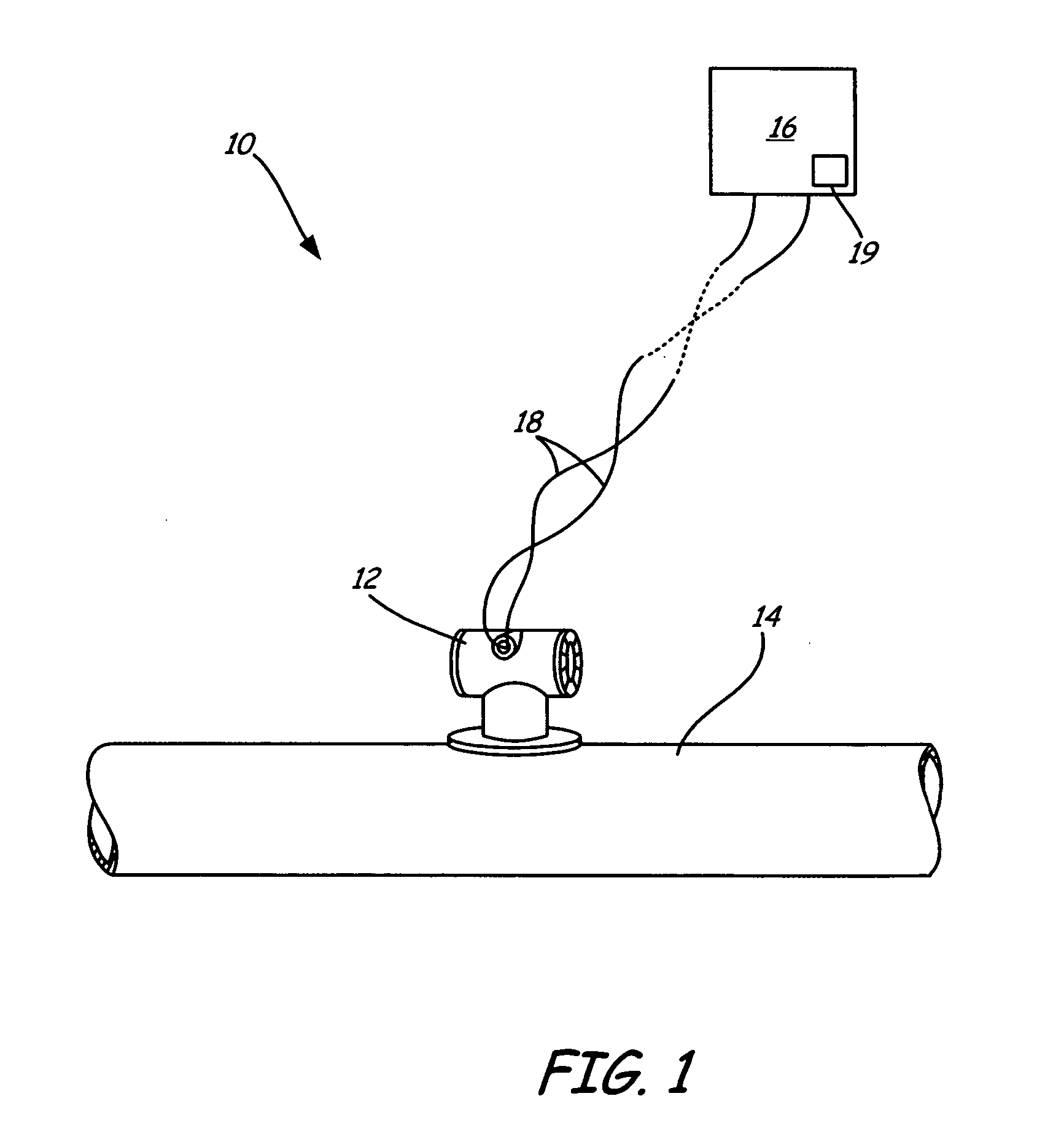
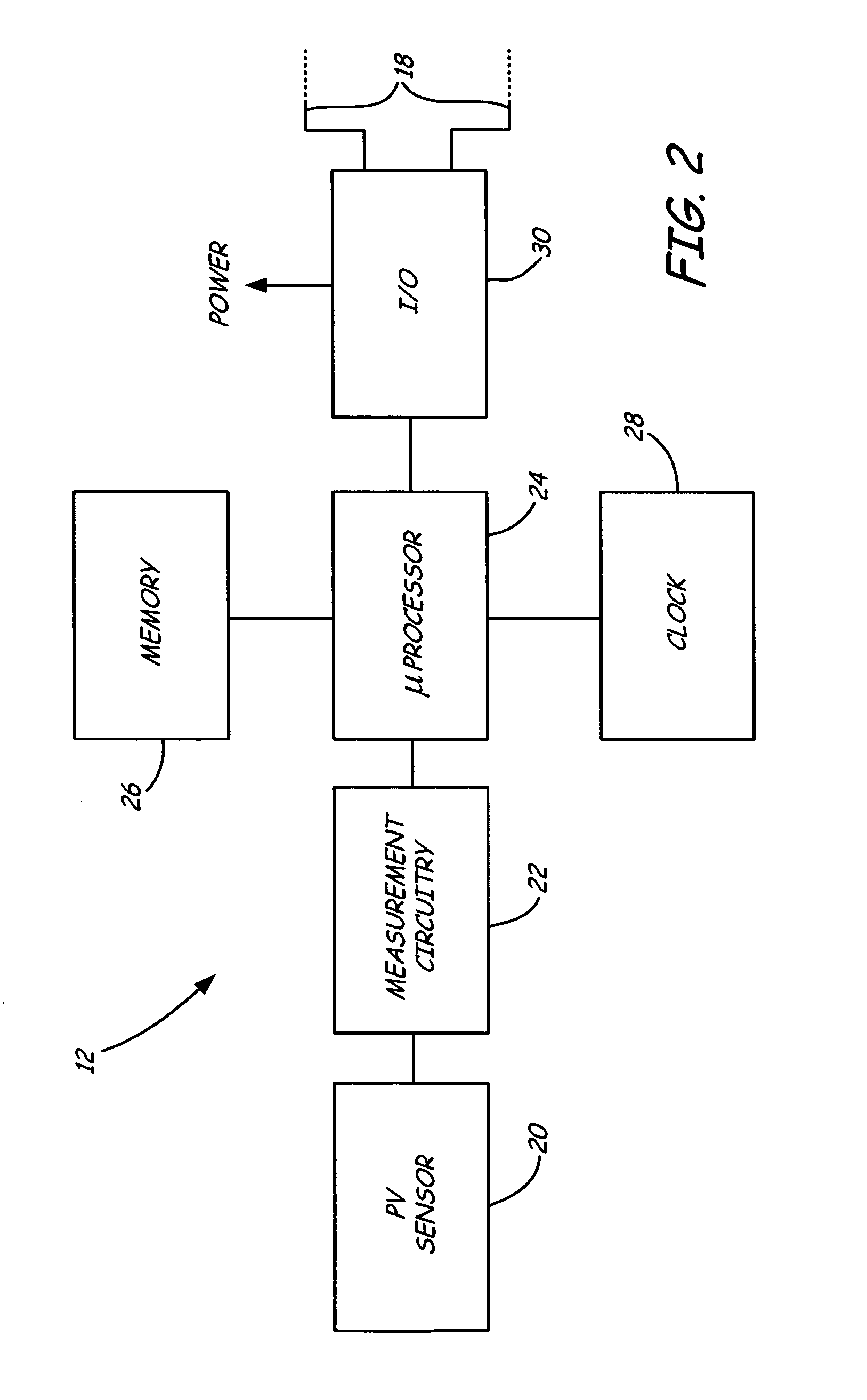
[0014] The present invention provides diagnostics for identifying wear or other degradation in industrial process components based upon an aggregate life span of the component. More specifically, the expected component life span is increased or decreased based upon the duration of time during which the component is exposed to different process conditions. With the present invention, the duration of time of the exposure is monitored and, along with a variable which quantizes the exposure, used to make a determination as to any increase or decrease in the expected lifetime of the component. In one example, a scaling factor is used to weight the exposure duration. In general, a histogram is created, which can be either a continuous or a discreet histogram, in which values of a measured process variable are correlated with a duration of time during which the process variable is at that value, or within a range of values. As a specific example, a particular section of piping may wear at ...


PUM


Abstract

A condition of an industrial process is diagnosed based upon process variable information related to a value of a measured process variable. Histogram information is calculated based upon the determined process variable information and time information related to a duration of time the measured process variable has the value. Condition of the industrial process is diagnosed based upon the calculated histogram information.

Description

BACKGROUND OF THE INVENTION [0001] The present invention relates to diagnostics of process control and monitoring systems for use with industrial processes. More specifically, the present invention relates to diagnostics which identify wear or degradation of components in industrial processes. [0002] Process control devices are used in industrial process control systems to monitor and / or control a process. A control device is a field device which is used to control the process and includes pumps, valves, actuators, solenoids, motors, mixers, agitators, breakers, crushers, rollers, mills, ball mills, kneaders, blenders, filters, cyclones, centrifuges, towers, dryers, conveyors, separators, elevators, hoists, heaters, coolers and others. A process variable transmitter is a field device which is used to measure a process variable such as temperature, flow, pressure, turbidity, pH and others. [0003] During operation of industrial processes, the various components used in the industrial ...

Claims


Application Information

Patent Timeline
Patent Type & Authority Applications(United States)
IPC IPC(8): G05B11/01
CPCG05B23/0232G05B2219/32234G05B2219/32226Y02P90/02Y02P90/80
Inventor FOSS, SCOT R.CURETON, TERRY A.
Owner MICRO MOTION INC
Why Eureka
Try Eureka