Methods and structures for reusing worker housing

Inactive Publication Date: 2007-11-29
ATCO STRUCTURES & LOGISTICS
58 Cites 1 Cited by

AI-Extracted Technical Summary

Problems solved by technology

Other times, where it is difficult or costly to move the units or the units are so site-specific as to render them of little value for reuse, the worker housing modules are simply abandoned or discarded.
After particularly large projects, many modules are discarded or abandoned due to oversupply.
Many modules are also di...

Method used

[0019] In one embodiment, for example, the invention allows for the conversion of a worker housing complex to structures for housing families that may need housing at or may be indigenous to the area of initial use of the complex. The structures can be, for example, configured as conventional detached, semi-detached or attached residential homes. The ability to reuse worker housing as family housing may offer significant economical benefits to the people responsible for the initial project, if the manufactured worker housing modules can be used in this manner in an area at or near the project site, including mitigating the costs of transporting the modules to another project and/or the costs of disposal if reuse as worker housing is not a viable option.
[0023] A truss 104 may be formed in various ways, but generally may include a roof rafter 140 including an inner end 140a and an outer end 140b. As will be appreciated a roof rafter may be alternately be termed a sloped chord, an inclined chord, a top chord, and various combinations thereof. In a worker housing module, the distance d that outer end 140b projects beyond the outer wall 12 on which it is supported may be minimized to reduce the effective projected size, also termed an overhang, of the structure's eave and thereby the width of the unit from interface I to outer end 140b. For example, as shown in the illustrated embodiment, the eave may be almost non-existent with overhang dista...

Benefits of technology

[0010] In accordance with another broad aspect of the present invention, there is provided a method for converting a worker housing module including a roof rafter to modify the appearance thereof, the method comprising: providing a worker housing module...

Abstract

A method for converting a worker housing module including a roof rafter to modify the appearance thereof, the method comprising: providing a worker housing module previously used to house workers in a dormitory style arrangement; exposing an outboard end of the roof rafter; and connecting a roof rafter extension to extend beyond the outboard end of the roof rafter to increase a roof eave projection on the structure.

Application Domain

Building roofsRoof covering using slabs/sheets +1

Technology Topic

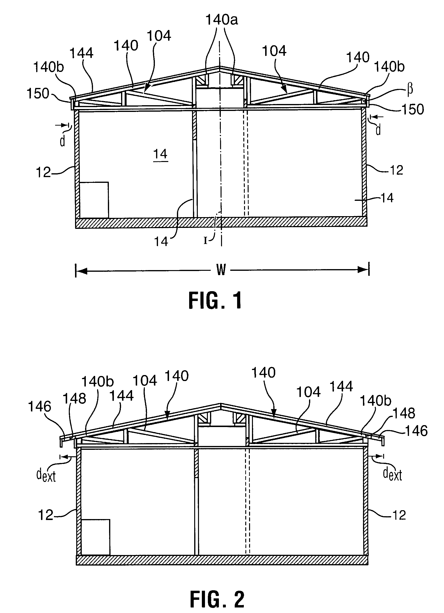
RafterEaves +1

Image

  • Methods and structures for reusing worker housing
  • Methods and structures for reusing worker housing
  • Methods and structures for reusing worker housing

Examples

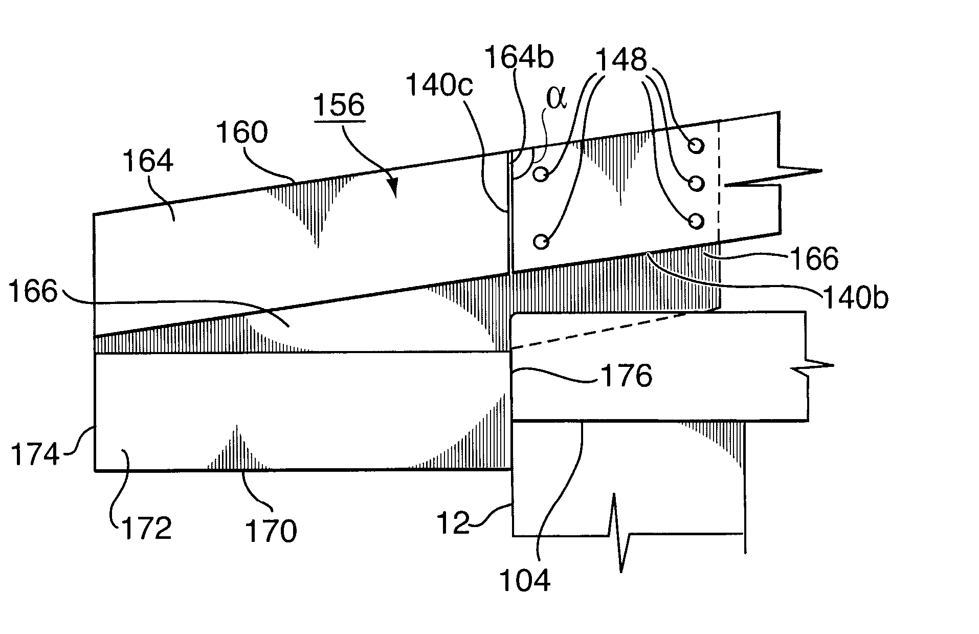
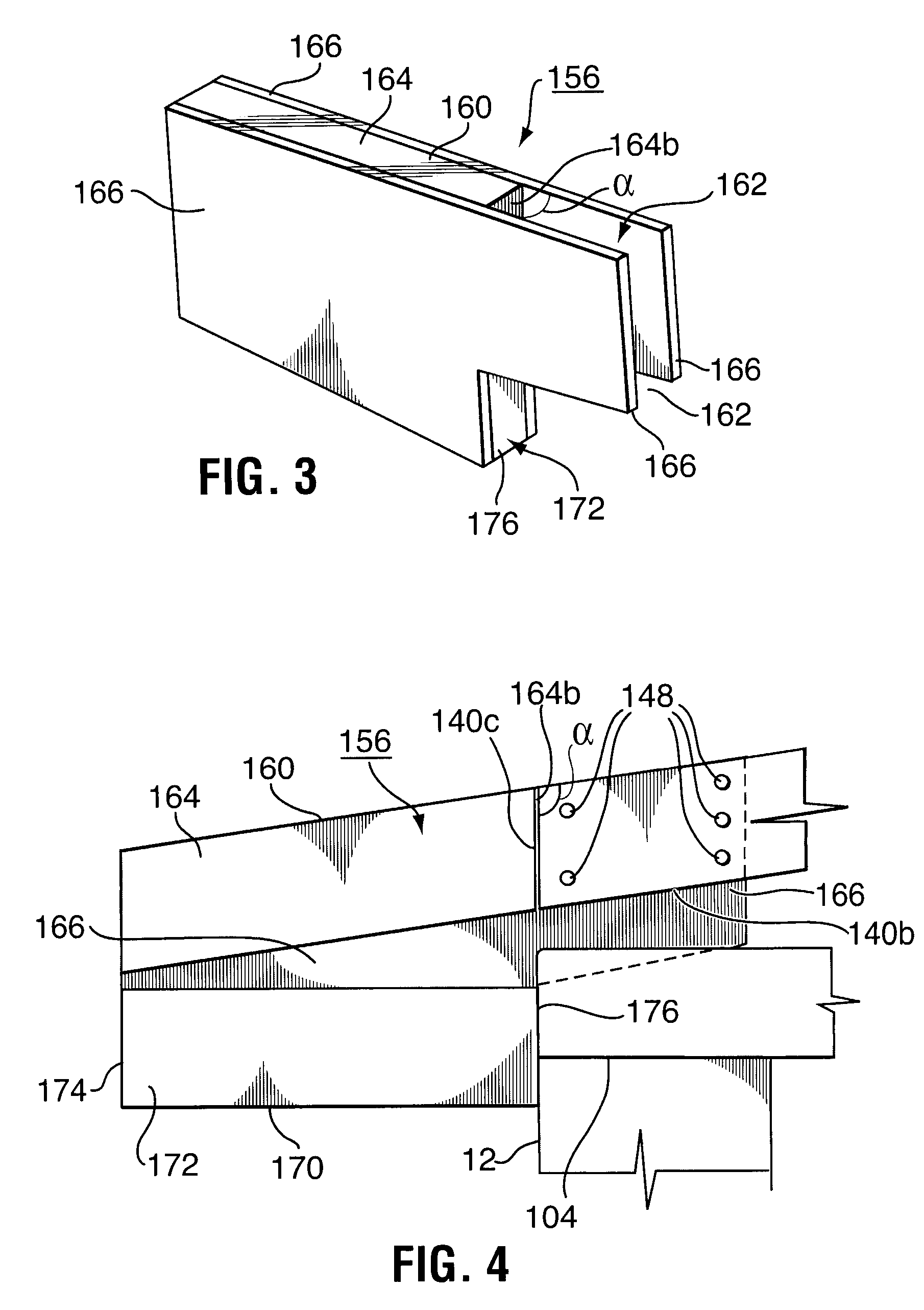
  • Experimental program(1)

Example

[0017] The detailed description set forth below in connection with the appended drawings is intended as a description of various embodiments of the present invention and is not intended to represent the only embodiments contemplated by the inventor. The detailed description includes specific details for the purpose of providing a comprehensive understanding of the present invention. However, it will be apparent to those skilled in the art that the present invention may be practiced without these specific details.
[0018] The invention considers reuse of worker housing in similar, or the same, applications at other sites or other projects as well as parameters governing reuse for alternate secondary purposes usually common to the area of initial use. Alternate secondary uses for manufactured worker housing modules according to the present invention can be, for example, office, commercial, smaller or reconfigured worker housing or residential family housing. For example, secondary uses can include structures having, for example, a combination of sleeping, messing, ablution and/or assembly areas for a population living within the confines of a specific building comprising one or more modules.
[0019] In one embodiment, for example, the invention allows for the conversion of a worker housing complex to structures for housing families that may need housing at or may be indigenous to the area of initial use of the complex. The structures can be, for example, configured as conventional detached, semi-detached or attached residential homes. The ability to reuse worker housing as family housing may offer significant economical benefits to the people responsible for the initial project, if the manufactured worker housing modules can be used in this manner in an area at or near the project site, including mitigating the costs of transporting the modules to another project and/or the costs of disposal if reuse as worker housing is not a viable option.
[0020] Some considerations for the planning, construction, and reuse of worker housing complexes are described in applicant's Canadian patent application 2,417,593, filed Jan. 29, 2003.
[0021] Worker modules and complexes are formed from worker units. The units may be constructed to be of a size suitable for transport, but are joined together at the job site to form the worker housing modules and complexes. A unit to be assembled into a worker housing complex has a size that allows it to be moved from a manufacturing plant to a job site where it will be used. This sometimes requires the unit to be transported thousands of miles. Due to transport restrictions, a unit has generally a limited width. As such, the eave is therefore generally minimized to permit the greatest width to be invested in the external walls and in the internal structure. While the eave may not be of particular interest for the worker housing structure, the eave may be of significant interest to a resident of family housing constructed from the reused worker housing unit.
[0022] Referring to FIG. 1, a worker housing module is shown, which is formed from at least a pair of units connected approximately along an interface plane, indicated at I. During transport and before the units are secured together to form the module, the units may be open and define a side limit along interface I. The module can include a roof formed from trusses 104 supported at least in part by exterior, outer walls 12. A worker housing unit also generally includes a plurality of internal walls 14, such walls 14 defining in many worker housing units dormitory-style accommodation including at least part of a centre hallway running from end to end in the unit, at least four bedrooms and possibly rooms for messing, ablution, working and/or gathering.
[0023] A truss 104 may be formed in various ways, but generally may include a roof rafter 140 including an inner end 140a and an outer end 140b. As will be appreciated a roof rafter may be alternately be termed a sloped chord, an inclined chord, a top chord, and various combinations thereof. In a worker housing module, the distance d that outer end 140b projects beyond the outer wall 12 on which it is supported may be minimized to reduce the effective projected size, also termed an overhang, of the structure's eave and thereby the width of the unit from interface I to outer end 140b. For example, as shown in the illustrated embodiment, the eave may be almost non-existent with overhang distance d being near 0. As noted, this arrangement may be selected to ensure that the worker housing units remain below the width acceptable for transport and with the major portion of their width defining the inner living space and wall structural requirements. Generally, a unit for transport including any eave thereon should be of a width w of less than 14 feet or possibly equal to or less than 12.5 feet.
[0024] When converting such worker units and modules to a residential dwelling, it may be desirable to change the appearance of the structure, for example, to less resemble a worker housing unit/module and/or to more closely resemble a standard house. One method of altering the appearance of the worker housing is to extend the projecting distance d of the eaves. With reference to FIG. 2, for example, the roof may be extended adjacent outer ends 140b of the rafters to increase the eave projection to a distance dext such that the structure may resemble a standard residential house. The extended length of the roof can, most conveniently, be increased by adding to the lengths of the roof rafters 140 and/or the roof sheathing 144, and/or by connecting an extension thereto and/or to the outer wall 12. For example, extensions such as boards 146 (as shown), metal tubes, sheathing, supports, etc. may be connected to the rafters, the sheathing and/or the outer wall by fasteners 148 (as shown), connectors, adhesives, straps, clips, webs, braces, etc.
[0025] In one embodiment, a worker housing structure including a roof rafter may be converted to a residence for a secondary purpose, by exposing an outboard end of a roof rafter, connecting a roof rafter extension to extend beyond the existing roof rafter end to create a roof eave projection on the structure. Thereafter, the roof rafter extension may be sheathed with any of roof sheathing, roofing, facia, soffit, etc.
[0026] To expose the roof rafter outboard end 140b, the existing facia 150 (FIG. 1), eaves trough, trim, roofing, etc. may have to be removed in whole or in part.
[0027] The roof rafter extension may be prepared on site as by cuffing boards (2×4, 2×6, wood, metal or polymeric rods, tubes, etc.) which are then secured to the structure. Alternately, in one embodiment, fabricated extensions may be used that are formed in a condition ready for securing to the exposed ends of the rafters.
[0028] With reference to FIGS. 3 and 4, an eave extension 156 is illustrated for extending the length of the eave on a structure such as is shown in FIG. 1 including a roof rafter 140 with an end 140b. The eave extension may include a roof sheathing support surface 160 and a connector, an example of same is described below, for securing to the structure to position the roof sheathing support surface in a position extending from the existing roof rafter end 140b.
[0029] In the illustrated embodiment, eave extension 156 is formed of a length of board 164 forming a roof sheathing support surface 160 and a pair of rigid surface webs 166, formed of material such as boards, wood sheeting, plywood, metal, structural plastic, straps, clips, brackets, etc., connected on either side of the board and extending therefrom to form an opening 162 between the webs extending beyond board 164. The opening 162 creates a slot that acts as a connector so that the extension can be positioned over end 140b of a rafter and secured thereon as by use of fasteners 148. In particular, when outer end wall/roof materials are removed, rafter end 140b is exposed with a space on either side. Webs 166 can be placed on either side of the exposed rafter so that the rafter extends into opening 162 and the webs are adjacent the rafter so that fasteners can be secured therethrough into the rafter, to secure the extension to the exposed end of the rafter.
[0030] Extension 156 including board 164 and webs 166 can be formed to permit the extension to fit onto and extend from the existing rafters for example to substantially follow a pitch corresponding to the existing roof pitch and a size to work with the original structure. For example, in one embodiment, board 164 can be selected to correspond with any required roof engineering parameters and opening 162 can be selected to fit easily over end 140b of the rafter on which it is to be installed. Board 164 may have an end 164b formed as by, for example, shaping, cutting and/or angling to butt against an end face 140c of rafter end 140b such that, as will be appreciated, the materials can be formed to transfer load such as to support the extension and any weight placed thereon. Webs 166 can be mounted on board 164 to urge installation of the extension to the rafter along a corresponding roof pitch. For example, the upper edge of webs 166 can extend from board 164 at an angle α relative to end 164a that corresponds with the roof pitch angle β (FIG. 1) in the structure on which the extension is to be installed.
[0031] Since the worker housing structures can be constructed with a plan for conversion, eave extensions may be prefabricated with consideration to the structure parameters such as rafter size, roof pitch, original and desired eave projected distance, etc.
[0032] If desired, as illustrated, extension 156 includes a soffit support surface 170, for example, provided by a lower board 172. A facia support surface 174 may also or alternately be provided, as by approximately forming ends of boards 164 and/or 172. Webs 166 may be formed to also secure lower board 172 or lower board 172 may be secured in some way to board 164.
[0033] If desired, a lateral support surface 176 may be provided to transfer load to an end of truss 104 or against side wall 12. A notch may be formed in the eave extension to allow installation of same with a lateral support surface. For example, webs 166 may extend out beyond lateral support surface 176 to ensure that there is sufficient material forming opening 162 to allow the extension to be slipped over the end of the rafter. Lateral support surface 176 can therefore be stepped back from the extension of webs 166 to extend adjacent or against an end of truss 104 or against outer wall 12.
[0034] The previous description of the disclosed embodiments is provided to enable any person skilled in the art to make or use the present invention. Various modifications to those embodiments will be readily apparent to those skilled in the art, and the generic principles defined herein may be applied to other embodiments without departing from the spirit or scope of the invention. Thus, the present invention is not intended to be limited to the embodiments shown herein, but is to be accorded the full scope consistent with the claims, wherein reference to an element in the singular, such as by use of the article “a” or “an” is not intended to mean “one and only one” unless specifically so stated, but rather “one or more”. All structural and functional equivalents to the elements of the various embodiments described throughout the disclosure that are known or later come to be known to those of ordinary skill in the art are intended to be encompassed by the elements of the claims. Moreover, nothing disclosed herein is intended to be dedicated to the public regardless of whether such disclosure is explicitly recited in the claims. No claim element is to be construed under the provisions of 35 USC 112, sixth paragraph, unless the element is expressly recited using the phrase “means for” or “step for”.

PUM

no PUM

Description & Claims & Application Information

We can also present the details of the Description, Claims and Application information to help users get a comprehensive understanding of the technical details of the patent, such as background art, summary of invention, brief description of drawings, description of embodiments, and other original content. On the other hand, users can also determine the specific scope of protection of the technology through the list of claims; as well as understand the changes in the life cycle of the technology with the presentation of the patent timeline. Login to view more.

Similar technology patents

User interface for controlling a household electrical appliance remotely connected thereto

ActiveUS20090118848A1easily and safely determined and setmodify their appearance
Owner:WHIRLPOOL CORP

Classification and recommendation of technical efficacy words

  • modify their appearance

User interface for controlling a household electrical appliance remotely connected thereto

ActiveUS20090118848A1easily and safely determined and setmodify their appearance
Owner:WHIRLPOOL CORP
Why Eureka
Try Eureka