
System and method for providing visual component layout input in alternate forms

a visual component and layout input technology, applied in the direction of instruments, computing, electric digital data processing, etc., can solve the problems of limiting the expressive and artistic application of artists/designers, unable to directly change the appearance of visual assets, and unable to arrange visual assets in a pleasing way

Active Publication Date: 2013-10-22
ADOBE SYST INC
View PDF17 Cites 3 Cited by
  • Summary
  • Abstract
  • Description
  • Claims
  • Application Information

AI Technical Summary

Benefits of technology

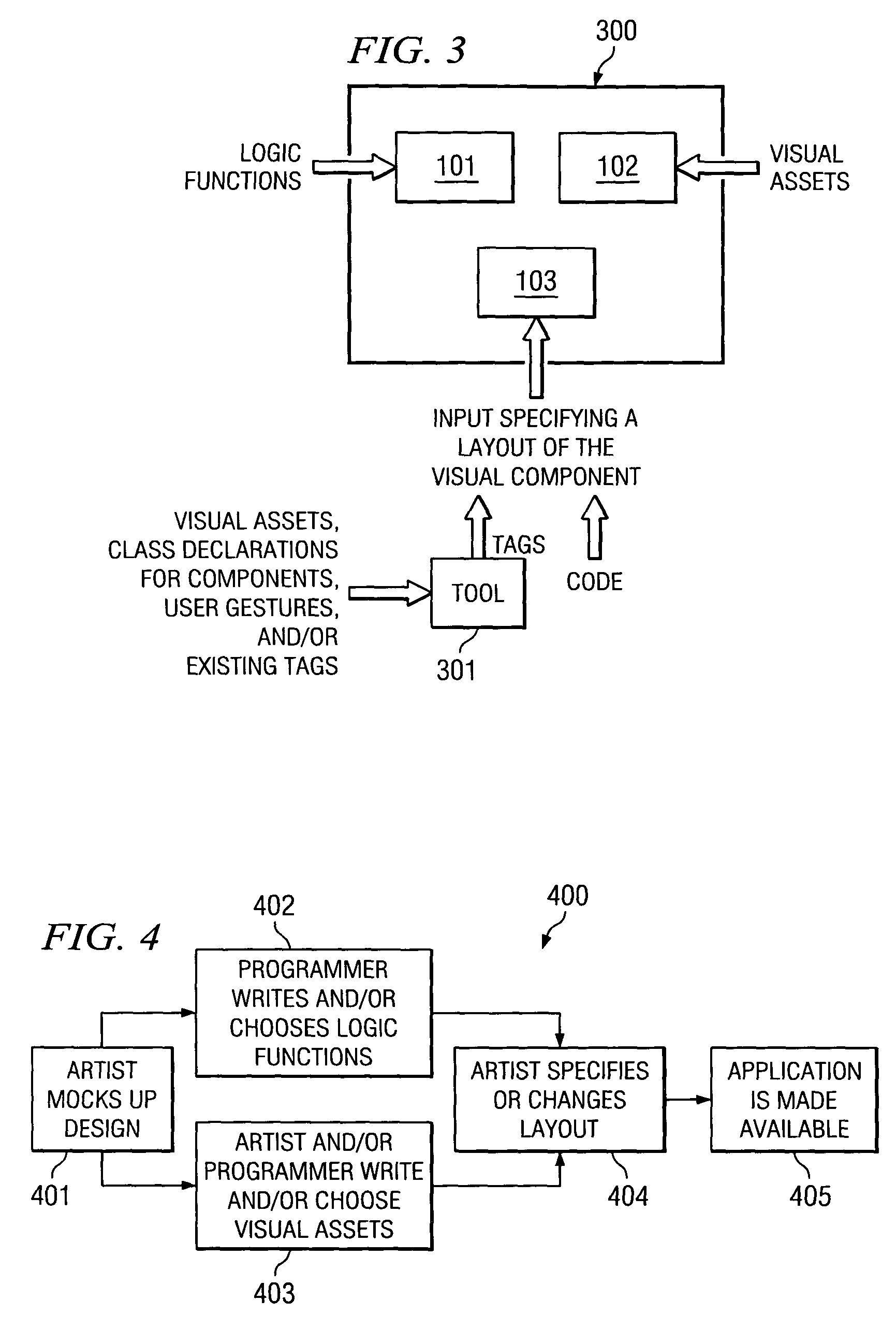
The present invention is a system, method, and computer program product that allows an artist to change the appearance of an application by using tag-based languages to describe the positional relationships of visual assets. This makes it easy for non-programmer artists to directly affect the tags. The system also allows for the development of tools that parse tags and provide a design view for the user. The appearance of an application can be modified through use of tags in both script-based and tag-based languages. Overall, this system allows for the layout of visual components to be defined using script and tags, and both developers and artists can be directly involved in the design of an application.

Problems solved by technology

Relying solely on code to create an application usually means that an artist / designer cannot directly change the appearance of visual assets because artists / designers are typically not programmers.
Thus, a disadvantage of having developers, rather than artists / designers, directly involved with all three of those pieces is that there is a limit to how expressive and artistic the application can be.
However, the programmer may, for example, fail to arrange the visual assets in a pleasing way, which is often a subtle task.
Application development can, therefore, be a frustrating, iterative experience when artists / designers are not able to directly affect the appearance of the application.
However, neither TRILLIAN™ nor WINAMP™ allows a programmer to contribute to the artwork using a script-based language.
Accordingly, there is no available technology that allows both artists / designers and programmers / developers to directly affect the artwork of an application.

Method used


Image

  • System and method for providing visual component layout input in alternate forms
  • System and method for providing visual component layout input in alternate forms
  • System and method for providing visual component layout input in alternate forms

Examples


Embodiment Construction

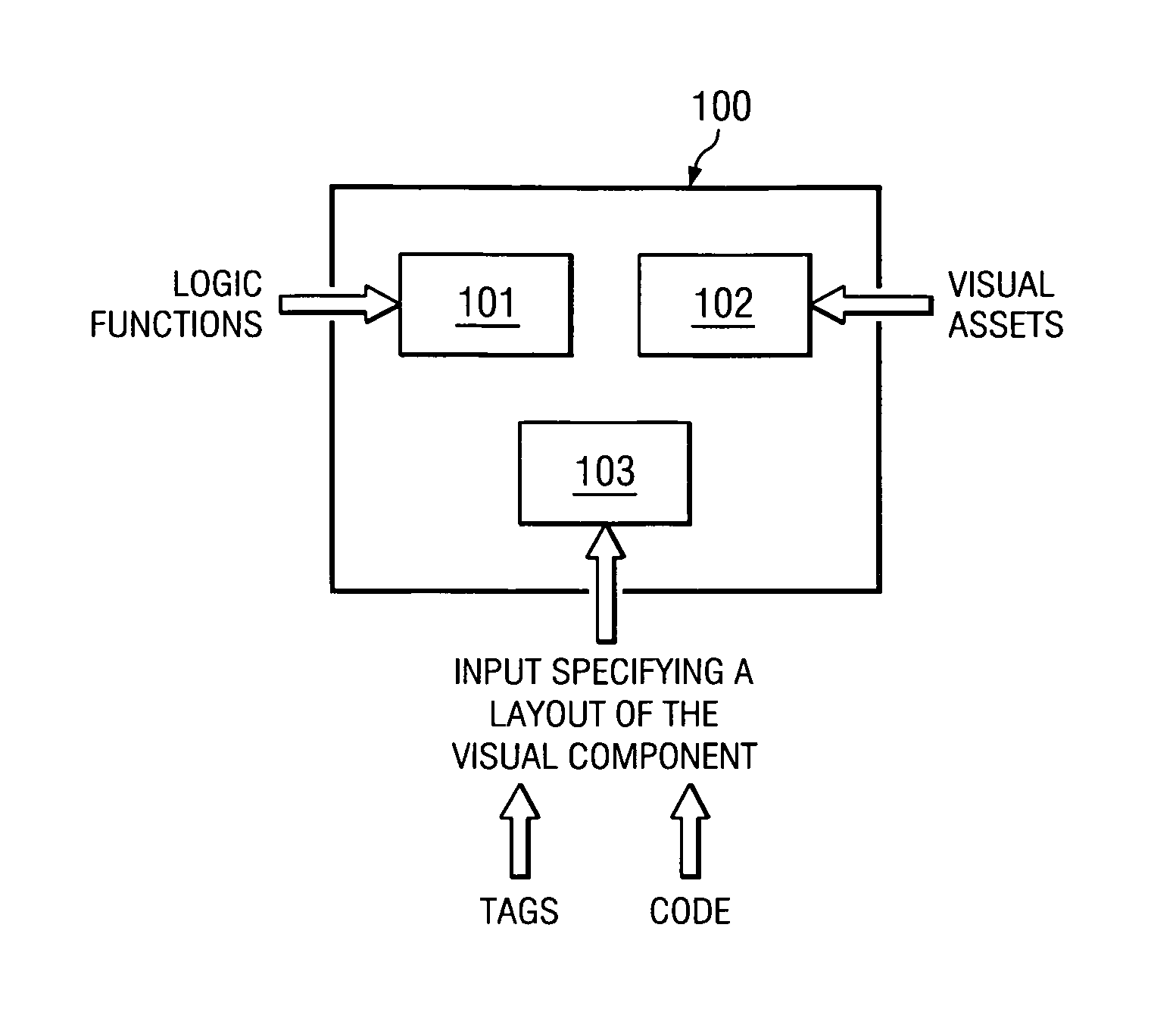
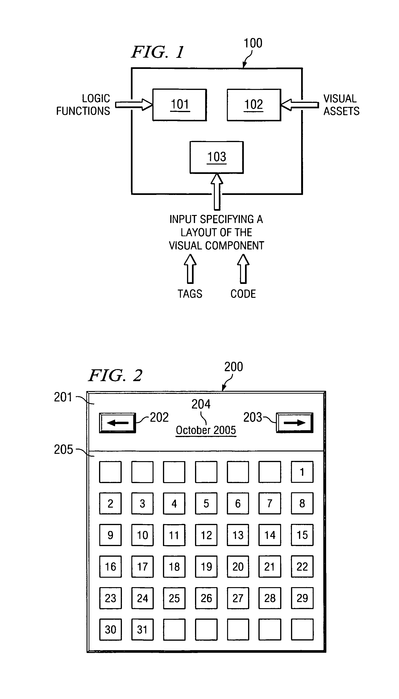
[0020]FIG. 1 is an illustration of example system 100 adapted according to one embodiment of the invention. In one specific example, system 100 is a FLEX™ compiler that is modified to compile a tag-based description of a layout of artwork (i.e., assets) in a visual component. System 100 includes three functional units 101-103.

[0021]Functional unit 101 receives input defining logic functions of a visual component. The input is usually in the form of code. For example, in a FLEX™ embodiment, a programmer uses ACTIONSCRIPT™ code to describe the various logic functions. It should be noted that ACTIONSCRIPT™ code is also used to create the class declaration of the component and the function to draw the various parts of the visual component. In fact, the input defining the logic functions and the class declaration for the component are usually included in the same file.

[0022]Functional unit 102 receives input defining the visual assets to be arranged in the component. Examples include ico...


PUM


Abstract

A system, method, and computer program product for creating a visual component in an application include a first functional unit operable to receive first input specifying logic functions of the visual component, a second functional unit operable to receive second input defining one or more visual assets to be included in a layout of the visual component, and a third functional unit operable to receive third input in alternate forms, said third input specifying one or more layouts of the visual component. The alternate forms may include tag input and script input.

Description

TECHNICAL FIELD[0001]The present invention relates in general to specifying the appearance of an application and specifically relates to specifying the appearance of visual components in an application.BACKGROUND OF THE INVENTION[0002]A variety of programs on the market allow a developer (e.g., a web developer) to create web pages, websites, interactive applications, and the like for use by end users (e.g., visitors to websites). Examples of such programs include DREAMWEAVER™ and FLEX BUILDER™, each available from MACROMEDIA INC., of San Francisco, Calif.[0003]DREAMWEAVER™ is an Integrated Development Environment (IDE) that allows web developers to design Hypertext Markup Language (HTML) web pages in a code editor and also in a graphical-based design time environment. In other words, DREAMWEAVER™ parses tags (e.g., HTML tags) and renders an interactive simulation of the application in the design time environment. Thus, a user may edit the application by directly editing the tags or ...

Claims


Application Information

Patent Timeline
Patent Type & Authority Patents(United States)
IPC IPC(8): G06F3/00
CPCG06F8/38
Inventor GREENFIELD, ELIOTGEORGE, DAVID
Owner ADOBE SYST INC
Learn More