Twisted Belt Transmission

a transmission and twisted belt technology, applied in the direction of belt/chain/gearing, friction gearing, belt/chain/gearing, etc., can solve the problems of reducing affecting the efficiency of the whole, and difficulty in specifying the toothing, so as to reduce the reduction ratio, increase the apparent radius of the driving pulley, and reduce the driving pulley. effect of radius

Inactive Publication Date: 2008-09-25
PH B INNOVATIONS SARL
View PDF8 Cites 1 Cited by
  • Summary
  • Abstract
  • Description
  • Claims
  • Application Information

AI Technical Summary

Benefits of technology

[0004]The invention provides a transmission system comprising a support structure and two pulleys, which pulleys are connected via a flexible element which may be a belt, a chain or any element known per se. This flexible element is wound onto the driving pulley while it is being unwound from the driven pulley and, through its thickness, gives the winding present on each pulley a spiral-wound pitch curve which increases the apparent radius of the driving pulley and decreases that of the driven pulley, thus reducing the reduction ratio and therefore being suitable for starting aids.
[0005]This flexible element adopts the position of a tangent to the pitch curves formed by the turns in situ, which means that these curves no longer have to remain tangential to one another as they did in the case of a gear set. There is therefore no longer any obligation to have mated curves or to adhere to a given inter-axis distance. It also becomes possible to change the direction of rotation by changing the direction of the windings. The pulleys may lie in the same plane with their axes parallel, but with a flexible element that will tolerate being twisted, it is possible to have axes that are non-parallel. In order to compensate for the variations in radius of the windings, guides position the flexible element in such a way that the strands tangential to the windings remain in the plane of the pulleys. It is possible to have an angle of up to 90° between the planes of the pulleys, just as a helical gear set of intersecting axes might achieve. In the case of coplanar pulleys, there is no need to have any guide and the flexible element follows the common tangent external to the windings in order to have the pulleys rotating in the same direction, or the internal common tangent with the pulleys rotating in opposite directions.
[0011]In one particular embodiment of the invention, the pulleys are mounted on one and the same shaft and are connected by at least two identical flexible elements guided by their own guide systems which guide systems are again identical. The objective of this is to spread the loads and ensure balance. It is sensible for the guide systems and the ends of the flexible elements to be positioned about the single shaft in a way that is also evenly distributed.
[0015]In one particular embodiment of the invention, the pulleys have a cylindrical hub and the corresponding end of the flexible element which is fixed to this hub has a thickness that continuously tapers down to zero. The length of this part may ideally be at least equal to the circumference of the hub. This allows the spiral-form pitch curve to be started without any apparent discontinuity in the radius and it is sensible to keep more than one turn in place in order to enhance, through the winding effect, the attachment of the end of the flexible element to the hub, which attachment is achieved by any system known per se, for example by adhesive bonding or using screws.
[0016]In one particular embodiment of the invention, the thickness of a working part of the flexible element varies in order to allow the variation in the apparent radius of the pitch curve to be modified. An increase in the thickness amplifies the customary spiral effect, the radius increasing on the driving pulley and decreasing on the driven pulley, whereas a reduction in the thickness reduces this effect and being able to cancel out this effect, keeping the radius constant, or even to reverse it.
[0017]In one particular embodiment of the invention, the outside diameter of at least one of the windings or a mark on the flexible element is used to control said system that has to be stopped at the end of the cycle if not before. This can be done in a number of ways either by measuring the outside diameter of one of the windings or using a mechanical, optical, magnetic or some other mark positioned on the flexible element. A simple mechanical embodiment with a roller rolling along the outside of the driving pulley would also make it possible to activate a control mechanism. This roller accompanies the increase in apparent radius and is able to for example to instigate the uncoupling of the pulley system and the engagement of the steady state transmission system. In the already-mentioned example of the bicycle, the arm carrying this roller would allow the front pulley to be uncoupled from the pedal crank axis and the conventional chain wheel to be coupled thereto.

Problems solved by technology

It becomes difficult to specify the toothing when the variations in radius are great and slippage at the contact faces of the toothing detracts from the efficiency of the whole.
In addition, rotations of these gear sets are limited to one revolution because they exhibit discontinuities if the radius varies in just one direction, unless provision is made for helical gearwheels like in French Patent Application No. 0406393, but then it becomes necessary to manage the longitudinal movement of the gearwheels and cope with other problems associated with the toothing.

Method used


Image

  • Twisted Belt Transmission
  • Twisted Belt Transmission

Examples


Embodiment Construction

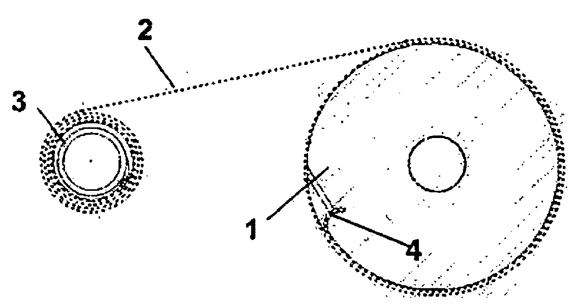
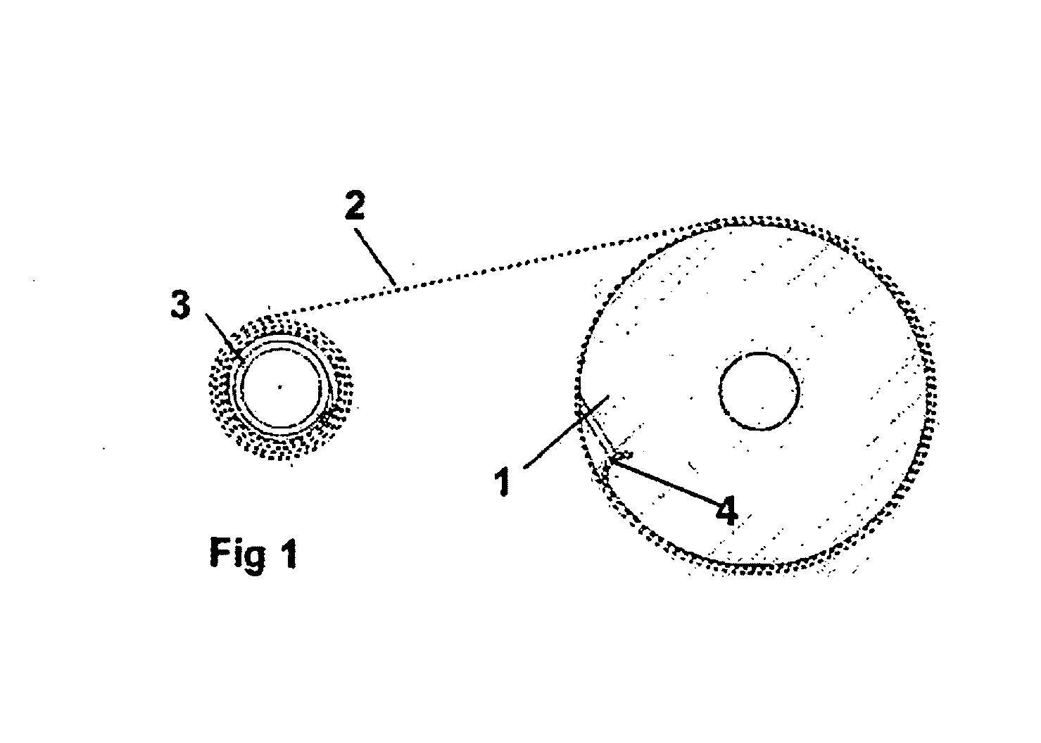
[0022]The driving pulley 1 rotates about the axis of the pedal crank mechanism and the driven pulley 3 about the axis of the rear wheel.

[0023]In the context of the application to the starting aid of a bicycle, the present system is normally used only in the phase of starting the bicycle. Thus, a coupling means intended either manually and / or automatically to select how the rear wheel of the bike is driven, namely either using the present transmission system or using the conventional transmission system employing a chain and rear sprocket(s) will advantageously also be provided. Whichever transmission is used, the driving force is applied to the driving pulley or to the front chain wheel, respectively, via the pedals.

[0024]In this variant, the pulleys 1 and 3 are preferably coplanar and the flexible element 2, which is a non-closed flat belt, is wound onto the pulley 1 while it is being unwound in the pulley 3, the two pulleys rotating in the clockwise direction. Because the pulleys ...


PUM


Abstract

The invention relates to a transmission mechanism with step-down reduction, in which an open belt (2) twists around a driving pulley (1) while being unwound from a driven pulley (2).

Description

TECHNICAL FIELD OF THE INVENTION[0001]The present invention relates to the field of mechanical transmissions with variable transmission ratio.BRIEF DESCRIPTION OF RELATED ART[0002]Gear transmissions in which the radius can vary and the inter-axis distance is fixed find applications in the field of starting aids like in French Patent Application No. 0309582 of Aug. 4, 2003, published on Feb. 11, 2005, in a coaxial set up, or in French Patent Application No. 0406393 dated Jun. 14, 2004, which has not yet been published, in a set up in which the axes are parallel. These are systems that do not operate continuously but operate during a phase in which a variation in velocity ratio is desired. In general, during these phases, the driving shaft remains driving and there are no problems with reversing the transmission as there are for example in the case of engine brakes. To manufacture these gear sets it is necessary to adhere to mated pitch curves in order to keep the inter-axis distance ...

Claims


Application Information

Patent Timeline
Patent Type & Authority Applications(United States)
IPC IPC(8): F16H19/00
CPCY10T74/19191F16H19/005
Inventor BAGGIO, JEAN-MARC
Owner PH B INNOVATIONS SARL
Why Eureka
Try Eureka