
Eureka
For R&D, Eureka makes reading and utilizing patents & technical documents easy.
Eureka AIR
Designed for self-driven R&D workflows. Generate viable solutions, solve complex R&D challenges, empower your innovation with AI.

Eureka Materials
Designed for material experts only. Revolutionize your material R&D, from search, analyze, to developing new materials.

TechResearch
Generate reliable direction feasibility study reports for your R&D in just a few steps.

TechSeek
Discover and master advanced knowledge NOW. Basics, ideas, possibilities, all at once.

TechMind
As an expert in R&D Theories, TechMind can generates customized viable solutions instantly.

TechRisk
Analyze your overall solution with one click, know your potential R&D risks in advance.

TechMonitor
Get weekly tech updates, stay abreast of the latest tech innovations and key insights.
Optical scanning device, enclosure of the same, method of configuring the same, and image forming apparatus
- Summary
- Abstract
- Description
- Claims
- Application Information
AI Technical Summary
Benefits of technology
Problems solved by technology
Method used
Image

Examples
first embodiment
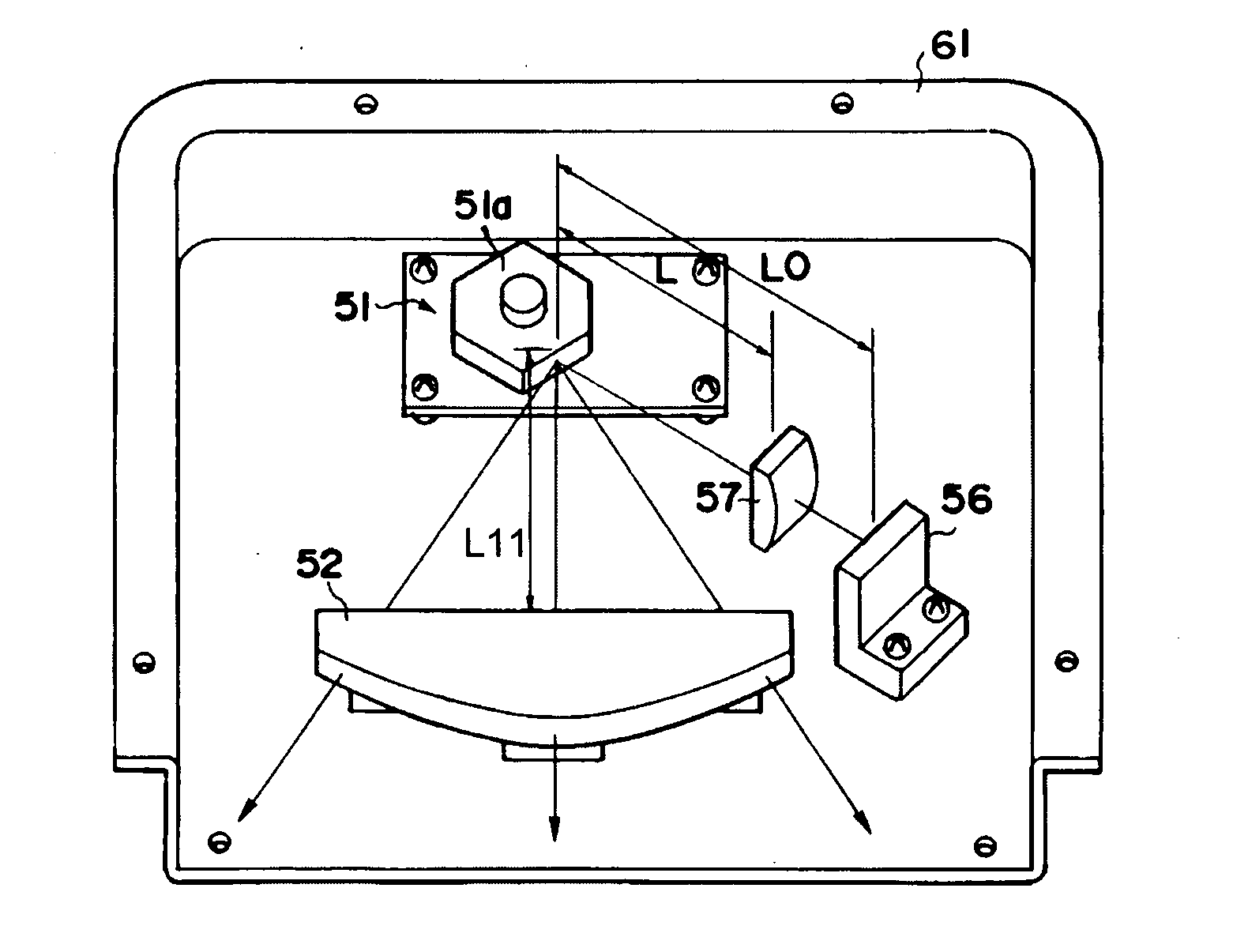
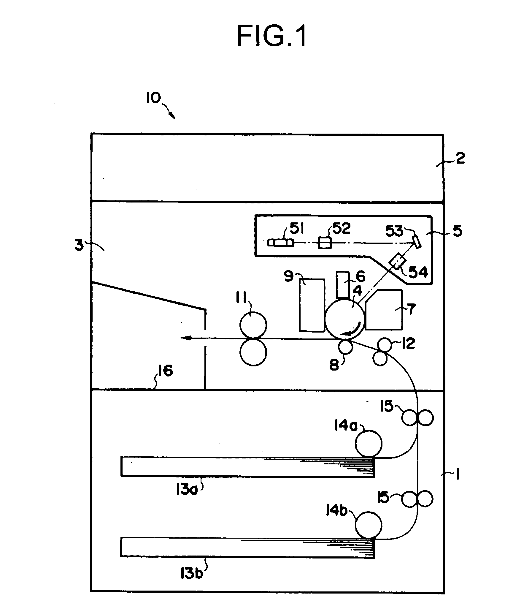
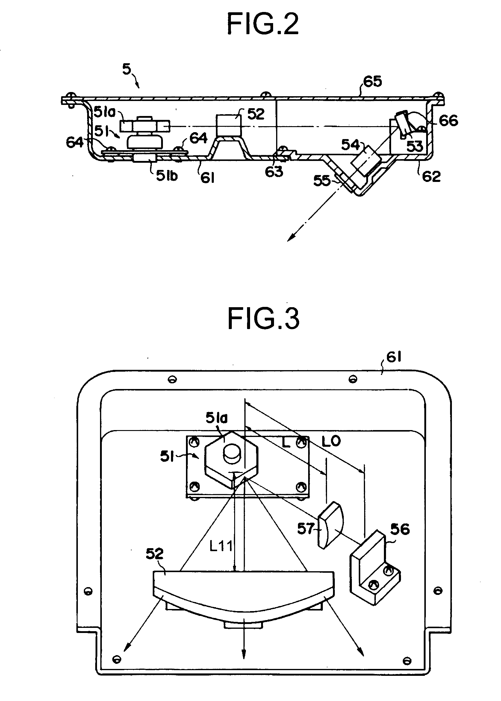
[0039]As an example of an image forming apparatus equipped with an optical scanning device, a digital copying machine 10 according the present invention is explained in detail below with reference to FIG. 1. The digital copying machine 10 includes a paper feeding unit 1, a scanner 2, and an imaging engine unit 3. The paper feeding unit 1, the scanner 2, and the imaging engine unit 3 are respectively arranged at the bottom, the top, and the center of the digital copying machine 10.
[0040]The imaging engine unit 3 includes a photoconductive drum 4 as an image carrier, an optical scanning device 5, a charger 6, a developing device 7, a transfer roller 8, a cleaning device 9, a pair of fixing rollers 11, and a pair of paper stop rollers 12. The charger 6, the developing device 7, the transfer roller 8, and the cleaning device 9 are arranged around the photoconductive drum 4. The optical scanning device 5 is arranged above the photoconductive drum 4, the charger 6, the developing device 7...
second embodiment
[0052]As another example of the image forming apparatus equipped with the optical scanning device, a laser printer 20 according the present invention is explained in detail below with reference to FIG. 4. The laser printer 20 includes a paper feeding unit 21 and an imaging engine unit 23. The paper feeding unit 21 is arranged at the bottom of the laser printer 20, and the imaging engine unit 23 is arranged on top of the paper feeding unit 21.
[0053]The imaging engine unit 23 includes a photoconductive drum 24 as an image carrier, an optical scanning device 25, a charger 26, a developing device 27, a transfer roller 28, a cleaning device 29, a pair of fixing rollers 31, a pair of paper stop rollers 32, and a pair of paper discharging rollers 37. The charger 26, the developing device 27, the transfer roller 28, and the cleaning device 29 are arranged around the photoconductive drum 24. The optical scanning device 25 is arranged on the slightly downward lateral side of the photoconducti...
third embodiment
[0061]As still another example of the image forming apparatus equipped with the optical scanning device, a color printer 70 according the present invention is explained in detail below with reference to FIG. 6. The color printer 70 includes a paper feeding unit 71 and an imaging engine unit 73. The paper feeding unit 71 is arranged at the bottom and the top of the laser printer 20, and the imaging engine unit 73 is arranged on top of the paper feeding unit 71.
[0062]The color printer 70 employs a four-drum tandem engine. The imaging engine unit 73 includes four imaging units 72C, 72M, 72Y, and 72Bk (for cyan (C), magenta (M), yellow (Y), and black (Bk) color respectively), a pair of fixing rollers 81, a pair of paper stop rollers 82, and a pair of paper discharging rollers 87.
[0063]The imaging units 72C, 72M, 72Y, and 72Bk are tandemly arranged in this order from the bottom. Each of the imaging units 72C, 72M, 72Y, and 72Bk has the same configuration except for a color of toner to be...
PUM
 Abstract
Description
Claims
Application Information
 - R&D Engineer
- R&D Manager
- IP Professional
- Industry Leading Data Capabilities
- Powerful AI technology
- Patent DNA Extraction
Browse by: Latest US Patents, China's latest patents, Technical Efficacy Thesaurus, Application Domain, Technology Topic, Popular Technical Reports.
© 2024 PatSnap. All rights reserved.Legal|Privacy policy|Modern Slavery Act Transparency Statement|Sitemap|About US| Contact US: help@patsnap.com