Method and apparatus for reliable communications in a packet network

a packet network and reliable technology, applied in the field of packet networks, can solve the problems of packet transmission faults, inability to meet the reliability requirements,

Active Publication Date: 2007-11-29
SBC KNOWLEDGE VENTURES LP
View PDF17 Cites 50 Cited by
  • Summary
  • Abstract
  • Description
  • Claims
  • Application Information

AI Technical Summary

Problems solved by technology

Much of the communications infrastructure used by these consumers is based on an Internet architecture which generally does not support the aforementioned reliability demands.
A packet transmission fault can occur for any number of reasons.

Method used


Image

  • Method and apparatus for reliable communications in a packet network
  • Method and apparatus for reliable communications in a packet network
  • Method and apparatus for reliable communications in a packet network

Examples


first embodiment

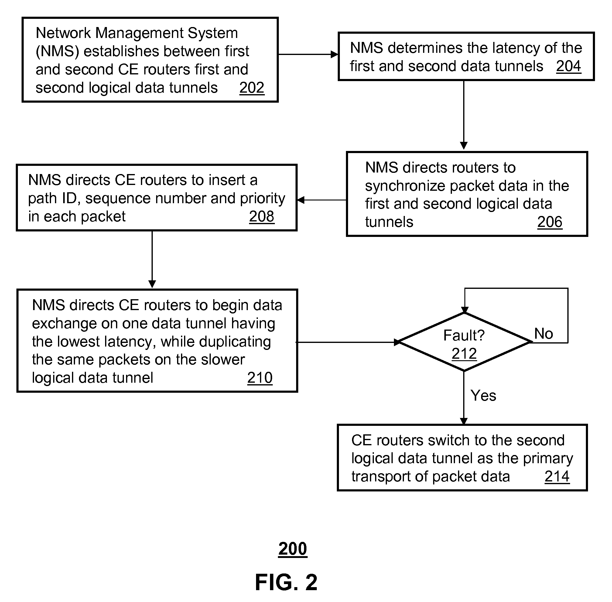
[0008]In the present disclosure, a network management system (NMS) can have a controller that manages a communications interface. The controller can be programmed to establish between first and second customer edge (CE) routers in a full mesh packet network a first logical data tunnel conforming to an isolation protocol, establish between the first and second CE routers a second logical data tunnel conforming to the isolation protocol, synchronize packet data in the first and second logical data tunnels, enable packet data exchanges between the first and second CE routers over the first logical data tunnel as a primary transport, direct the first and second CE routers to duplicate the packet data exchanged between them over the second logical data tunnel, and direct the first and second CE routers to synchronously switch to the second logical data tunnel as the primary transport of packet data upon detecting a fault in the first logical data tunnel.

second embodiment

[0009]In the present disclosure, a computer-readable storage medium in a network management system (NMS) can have computer instructions for establishing between first and second routers of a packet network first and second logical data tunnels conforming to an isolation protocol, enabling packet data exchanges between the first and second routers over the first logical data tunnel, and directing the first and second routers to duplicate the packet data exchanged between them over the second logical data tunnel when said first and second routers switch from the first logical data tunnel to the second logical data tunnel as a primary transport of packet data.

third embodiment

[0010]In the present disclosure, a computer-readable storage medium in a first routing element, can have computer instructions for initiating packet data exchanges with a second routing element over a first logical data tunnel as a primary means for exchanging information, and duplicating the packet data exchanged with the second routing element over a second logical data tunnel when said first and second routers switch from the first logical data tunnel to the second logical data tunnel as a primary transport of packet data upon detecting a fault in the first logical data tunnel.

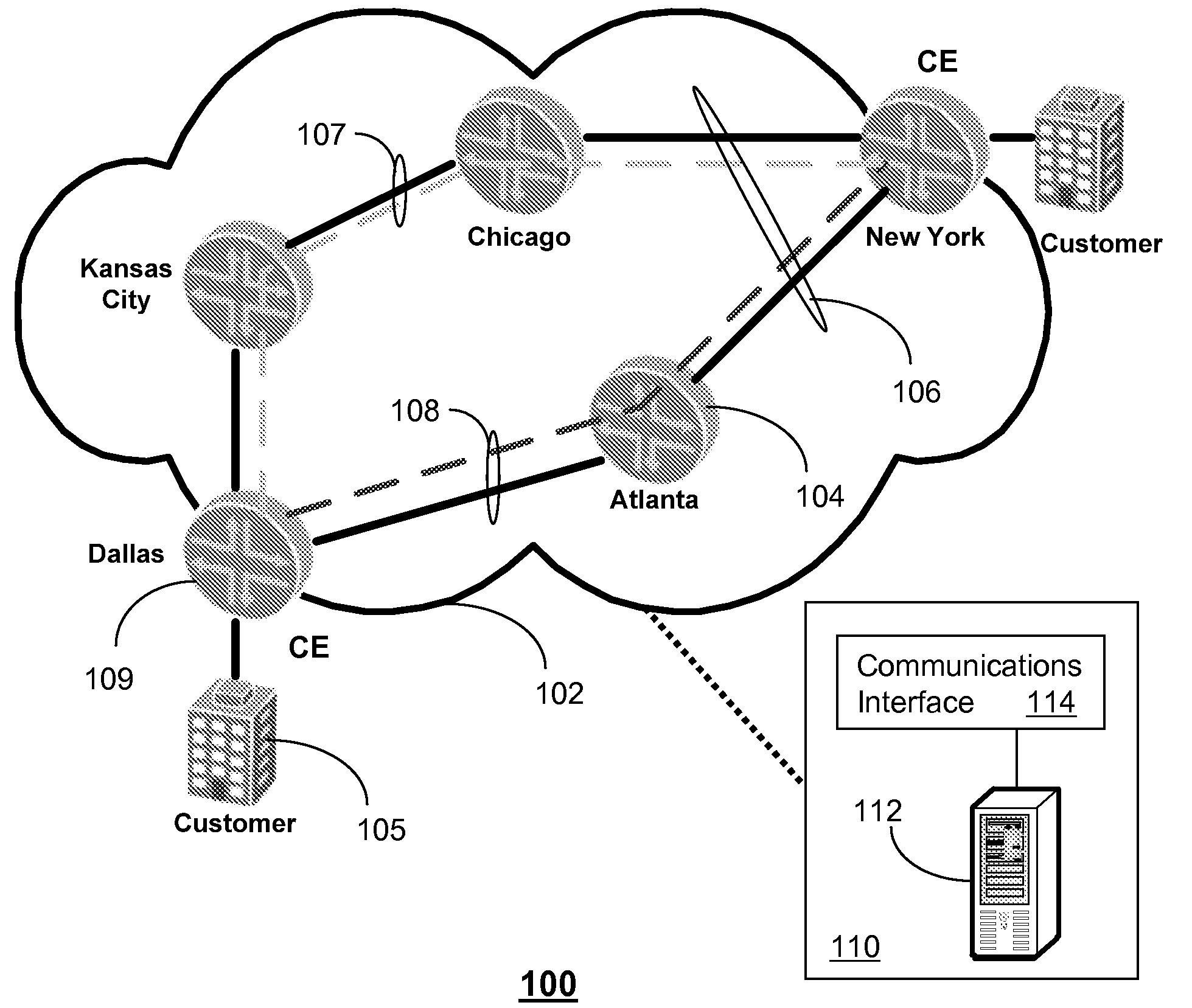
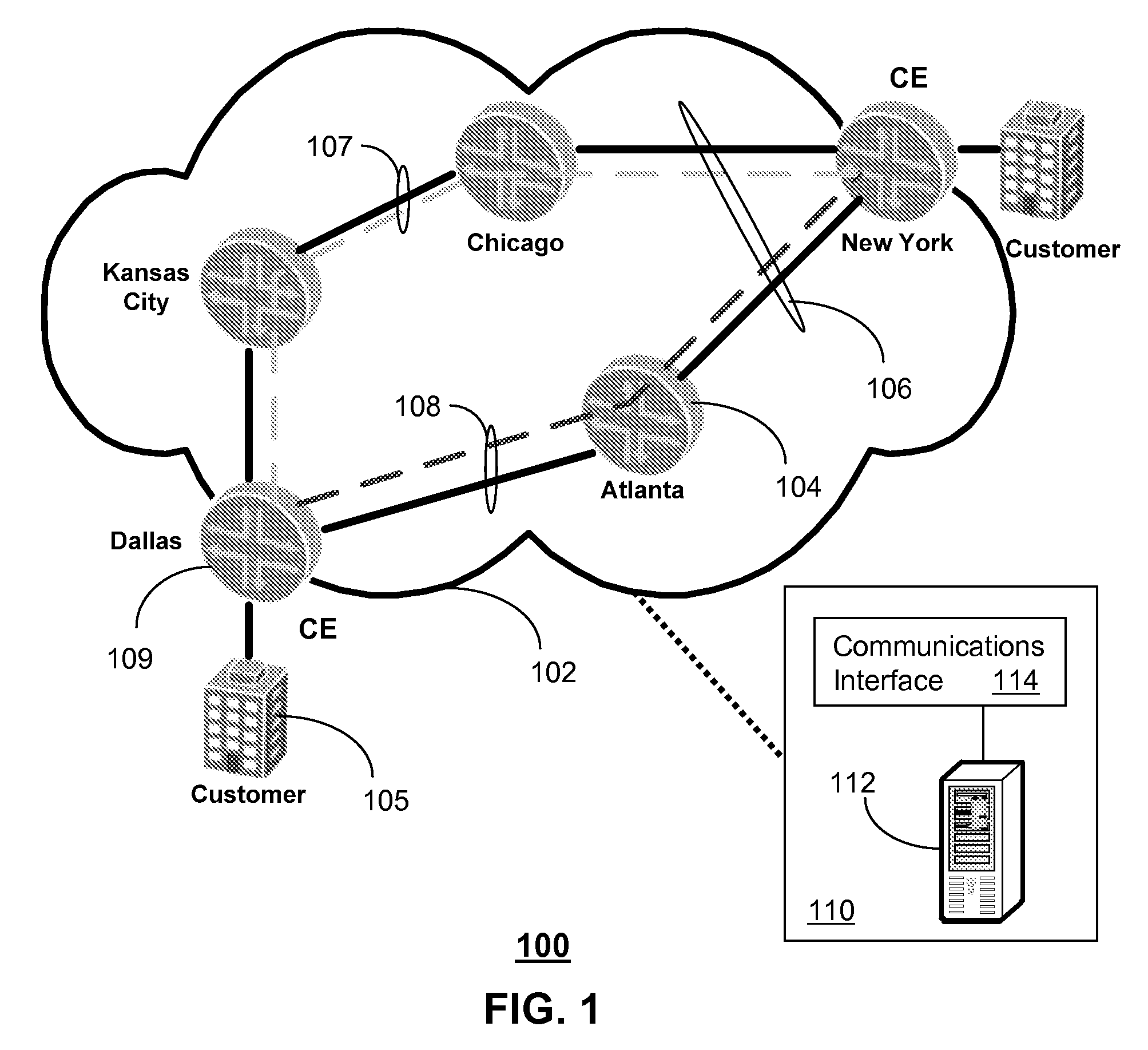
[0011]FIG. 1 is a block diagram of a communication system 100. The communication system 100 can comprise a packet network 102 having a number of routers 104 for establishing a number of logical data tunnels 106 between one or more customer edge (CE) routers 109. The packet network 102 can comprise, for example, a full mesh multi-protocol label switching (MPLS) network (for illustration purposes only, the pa...


PUM


Abstract

A system and method are disclosed for reliable communications in a packet network. A system that incorporates teachings of the present disclosure may include, for example, a network management system (NMS) having a controller programmed to establish between first and second customer edge (CE) routers in a full mesh packet network first and second logical data tunnels conforming to an isolation protocol, synchronize packet data in the first and second logical data tunnels, enable packet data exchanges between the first and second CE routers over the first logical data tunnel, direct the first and second CE routers to duplicate the packet data exchanged between them over the second logical data tunnel, and direct the first and second CE routers to synchronously switch to the second logical data tunnel upon detecting a fault in the first logical data tunnel.

Description

FIELD OF THE DISCLOSURE[0001]The present disclosure relates generally to packet networks, and more specifically to a method and apparatus for reliable communications in a packet network.BACKGROUND[0002]Consumers such as law enforcement agencies, banks, financial institutions and so on in some applications require reliable communications with preferably no interruptions or minimal loss of data transport. Much of the communications infrastructure used by these consumers is based on an Internet architecture which generally does not support the aforementioned reliability demands.[0003]A need therefore arises for a method and apparatus for reliable communications in a packet network.BRIEF DESCRIPTION OF THE DRAWINGS[0004]FIG. 1 depicts an exemplary block diagram of a communication system;[0005]FIG. 2 depicts an exemplary method operating in a number of network elements of the communication system; and[0006]FIG. 3 is a diagrammatic representation of a machine in the form of a computer sys...

Claims


Application Information

Patent Timeline
Patent Type & Authority Applications(United States)
IPC IPC(8): H04L12/28
CPCH04L41/06H04L41/0803H04L45/28H04L45/22H04L45/24H04L45/00
Inventor SCHOLL, THOMASJOY, JENNIFERWEBER, MARKUS
Owner SBC KNOWLEDGE VENTURES LP
Why Eureka
Try Eureka