

Fixing device and image forming apparatus
- Summary
- Abstract
- Description
- Claims
- Application Information
AI Technical Summary
Benefits of technology
Problems solved by technology
Method used
Image

Examples
example 1
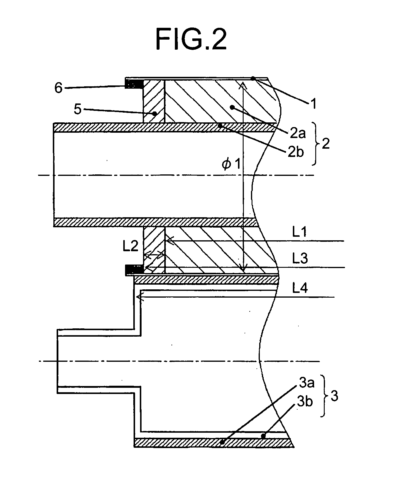
[0038]FIG. 2 is a cross section of the fixing sleeve 1, the fixing roller 2, and an area near the end of the pressure roller 3 according to Example 1.
[0039]In the fixing device having the configuration mentioned above, the fixing roller 2 has an outer diameter φ1 of 40 millimeters and a body-portion length L1 of 320 millimeters, for example. The body portion includes at its end a high-stiffness ring 5 formed of silicone rubber with Asker C hardness of, for example, 60, which is higher than that of the elastic layer of the fixing roller 2 with Asker C hardness of, for example, 20 to 50. The ring has an outer diameter of 40 millimeters and a width L2 of 5 millimeters. On the inner circumference of the end of the fixing sleeve 1, a guide 6 made of heat-resistant silicone rubber is adhered to the entire area in the circumferential direction. The guide 6 serves as a shift stop and protrudes from the inner circumference surface to the inner diameter center direction. With the guide 6 abut...
example 2
[0045]FIG. 3 is a cross section of the fixing sleeve.1, the fixing roller 2, and the pressure roller 3 that constitute the fixing device according to Example 2.
[0046]In the fixing device of Example 2, an outer diameter φ2 of the fixing roller 2 and the ring 5 is 35 millimeters, and an inner diameter φ3 of the guide 6 is 36 millimeters. In this configuration, in use, the fixing sleeve 1 and the fixing roller 2 make contact with each other by being pressed by the pressure roller 3, and form a nip portion with the pressure roller 3. Therefore, the guide 6 provided at the end of the fixing sleeve 1 and the ring 5 provided at the end of the fixing roller 2 abut at least on the nip portion, thereby achieving a shift-stopping effect. On the other hand, when disassembled, the fixing sleeve 1 and the fixing roller 2 is released from the pressure of the pressure roller 3, thereby not forming a nip portion. With this, the fixing sleeve 1 can be in a non-contact state without being pressed by t...
example 3
[0047]FIG. 4 is a cross section of the fixing sleeve1, the fixing roller 2, and the pressure roller 3 that constitute the fixing device according to Example 3.
[0048]In the fixing device having the configuration mentioned above, the ring 5 and the guide 6 are provided only on one side of the ends. As shown in FIG. 4, the pressure lever 7 supported at its both bottoms by a fulcrum 8 is pressed by a spring 9, thereby forming a pressure nip between the fixing roller 2 and the pressure roller 3. The pressure of the compression spring can be adjusted by a pressure adjusting screw 10, and the parallelism between the fixing roller 2 and the pressure roller 3 can also be adjusted. The parallelism can be adjusted by, since the fixing roller 2 is fixed, pressing up the core metal 3b of the pressure roller 3 and the pressure lever 7 in an upward direction in FIG. 4. When the parallelism is adjusted, the shifting direction of the fixing sleeve 1 is adjusted to a side where the ring and the guide...
PUM
 Abstract
Description
Claims
Application Information