Energy translating footwear mechanism for enhancing forward

a technology of energy-transmitting footwear and forward enhancement, which is applied in the field of athletic shoe technology to achieve the effect of reducing the risk of injury and dissolving the shock of foot strik

Inactive Publication Date: 2007-12-13
MULLEN KRISTYNA +3
View PDF18 Cites 64 Cited by
  • Summary
  • Abstract
  • Description
  • Claims
  • Application Information

AI Technical Summary

Benefits of technology

[0024] In another aspect, systems and methods of the present invention promote more efficient running technique by facilitating foot-strike to occur at a point under and behind the runner's center of gravity. This is accomplished by the foot-strike member, angular displacement member and balance-thrust member working cooperatively to displace the runner's center of gravity and translate gravitational, inertial and ground reaction forces, as well as muscular tension forces, into linear momentum.
[0031] Other aspects of the present invention provide systems and methods to effectively displace the runner's center of gravity and translate gravitational, inertial and ground reaction forces into linear momentum. In another aspect, the present invention provides a platform that provides a rotational base for dissipating the shock of foot strike, thereby providing a more comfortable running shoe, which helps reduce the risk of injury associated with forceful foot strike.

Problems solved by technology

The foregoing and other known prior art have fundamental disadvantages in that they are not directed at improving efficiency by synchronizing the three basic phases of the human running cycle, seen illustrated in FIGS. 6A-6C with elements on the shoe that optimize momentum, efficiency, and fluidity of motion through the cycle.

Method used


Image

  • Energy translating footwear mechanism for enhancing forward
  • Energy translating footwear mechanism for enhancing forward
  • Energy translating footwear mechanism for enhancing forward

Examples


Embodiment Construction

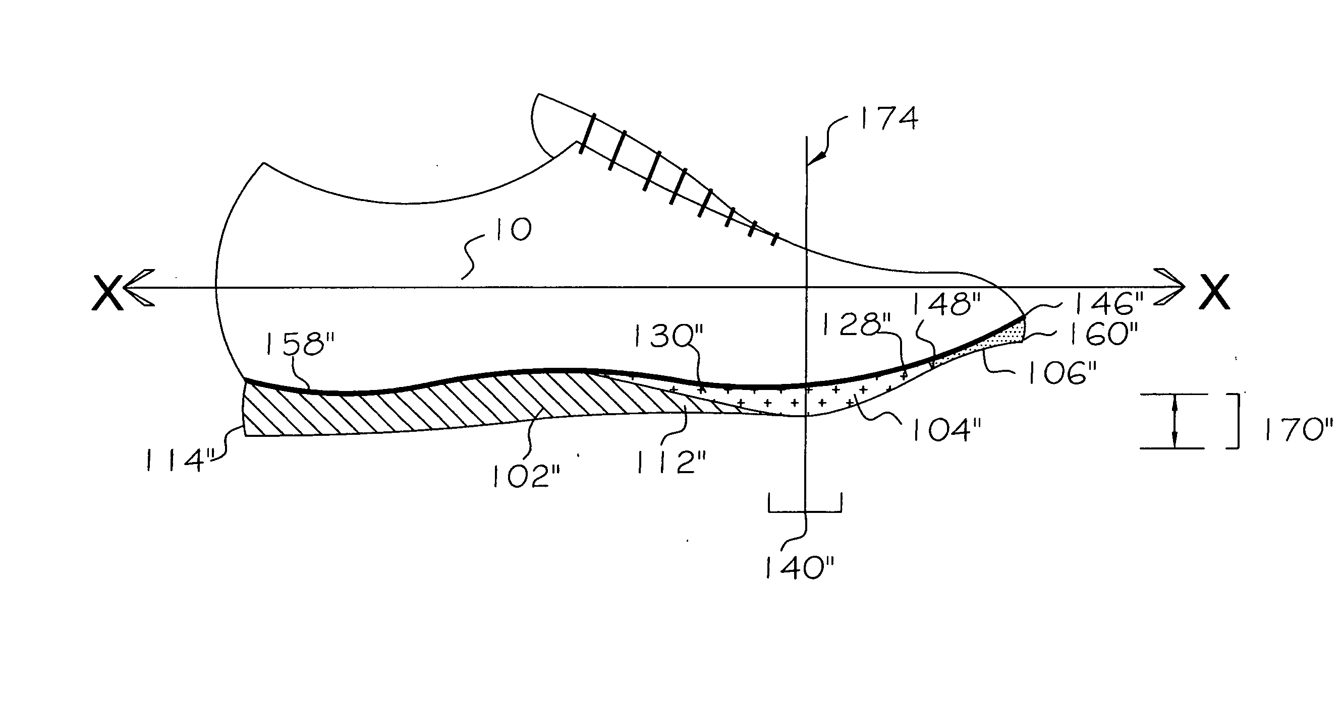
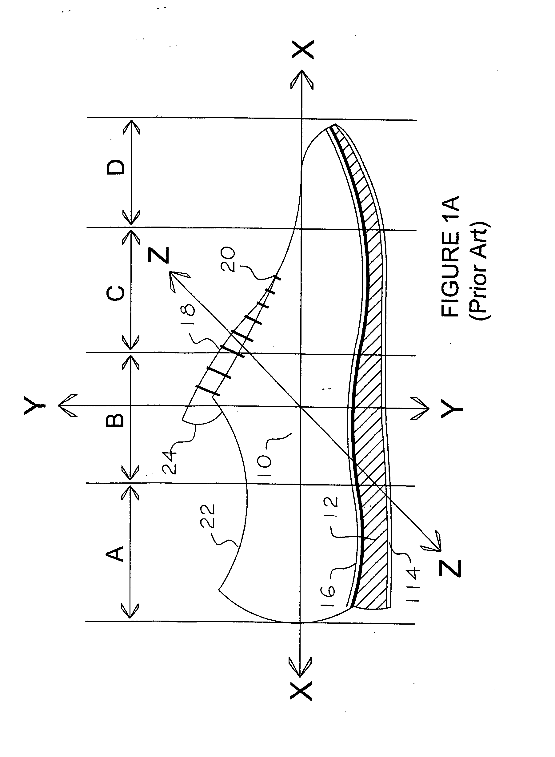
[0045] While the invention may be embodied in different forms to achieve more optimal centering of mass, the specific embodiments shown in the figures and described herein are presented with the understanding that they are exemplary of the principles of the invention and are not intended to limit the invention to that specifically illustrated and described herein. FIG. 1A shows a generic form of footwear comprising an upper, indicated generally as 10, and a sole unit which generally may comprise (i) a midsole for energy absorption and / or return; (ii) an outsole material for surface contact and abrasion resistance and / or traction; or (iii) a single unit providing such midsole or outsole functions. For example, the sole unit shown in FIG. 1A includes a midsole 12, an outsole 114 and an insole 16 on the interior lower surface of the footwear. The sole unit can cover some or all of the area of the supported foot.

[0046] As is well known in the art, the sole unit may include resilient el...


PUM

PropertyMeasurementUnit
distanceaaaaaaaaaa
distanceaaaaaaaaaa
distanceaaaaaaaaaa

Abstract

The present invention provides soles, platforms, or inserts incorporated into footwear, preferably athletic footwear, designed to promote a more efficient running technique by an energy-translating sole comprising one or more angular displacement members, balance-thrust members, and counterbalance as well as conventional features. Systems and methods of the present invention promote more efficient running technique by facilitating foot-strike to occur at a point under and behind the runner's center of gravity. This may be accomplished, for example, by a foot-strike member, angular displacement member and balance-thrust member working cooperatively to displace the runner's center of gravity and translate gravitational, inertial and ground reaction forces, as well as muscular tension forces, into linear momentum.

Description

CROSS REFERENCE TO RELATED APPLICATIONS [0001] This application is a divisional application of co-pending application Ser. No. 10 / 847,731 filed May 18, 2004 and application Ser. No. 10 / 045,299 filed on Oct. 23, 2001, which claim priority to provisional application No. 60 / 242,742, filed on Oct. 23, 2000, and to PCT patent application No. PCT / US01 / 51382, filed on Oct. 23, 2001, which also claims priority to provisional application No. 60 / 242,742, filed on Oct. 23, 2000. The priority of the prior applications is expressly claimed and their disclosures are hereby incorporated by reference in their entirety.BACKGROUND OF THE INVENTION [0002] 1. Field of the Invention [0003] The present invention relates to athletic shoe technology. More particularly, it relates to systems and methods for various forms of energy-translating soles, or platforms, or inserts, which are incorporated into footwear and are designed to more effectively transfer gravitational, inertial and ground reaction forces ...

Claims


Application Information

Patent Timeline
Patent Type & Authority Applications(United States)
IPC IPC(8): A43B13/14A43B5/00A43B13/12A43B13/18
CPCA43B5/06A43B7/1425A43B7/1435A43B7/1445A43B7/145A43B17/00A43B13/14A43B13/145A43B13/146A43B13/148A43B13/188A43B13/12A43B13/00A43B21/30A43B1/10
Inventor TALBOTT, DANIEL ARTHUR
Owner MULLEN KRISTYNA
Why Eureka
Try Eureka