Percutaneous access conduit and methods

a percutaneous access and conduit technology, applied in the field of medical procedures and instruments, can solve the problems of increased risk of arterial trauma and tearing of the vessel wall, increased risk of artery failure, and more difficult hemostasis at the end of the procedure, so as to reduce the bleeding

Inactive Publication Date: 2007-12-13
GRAYZEL JEFFREY +5
View PDF53 Cites 9 Cited by
  • Summary
  • Abstract
  • Description
  • Claims
  • Application Information

AI Technical Summary

Benefits of technology

[0029] Accordingly, to achieve the desired visualization of the operative site and the proper positioning of the needle to achieve the most effective puncture of a vessel, the present invention sets forth several coacting combinations of coacting instruments, some capable of independent action, as well as enabling clear visualization of the operative area, precise location of the operative site, capture and immobilization of the vessel, and guidance in the positioning and insertion of the puncturing needle.
[0030] Visualization of the operative area is accomplished by means of a dissecting-retracting tool with the hand-gripping and controlling members of the tool offset in two dimensions from angled blunt dissecting fingers to create a subcutaneous path from skin to vessel, providing a clear line of sight through the dissecting fingers to their very tips. Once visualized that dissection has occurred, conduit and obturator / carrier assemblies are matingly positioned within the blunt dissecting fingers to register with the ends of the dissecting fingers at the site of the blood vessel. The terminal ends of the conduit and obturator are angled and concavely shaped to conform to the vessel, and center the assembly on top of the vessel to be punctured. The dissector-retractor is removed and the obturator is then removed leaving the conduit in place and thus providing an open channel from skin to vessel surface. The conduit bears along its lower, inner surface a fine longitudinal groove capable of guiding a needle tip to the center of the blood vessel or, alternatively, guiding a light probe to illuminate the puncture site. This light probe along its upper surface carries a fine longitudinal groove that is also capable of guiding the needle to the center of the blood vessel. The light probe is centered within the conduit by mating a raised ridge along the longitudinal axis on the underside of the probe with the longitudinal groove located on the surface of the conduit. Centering of the illumination probe on the vessel is facilitated by a forked tip which captures the blood vessel equally on either side of the midline of the probe, and in the case of an artery, transmits arterial pulsations in a manner that enables the operator to feel that the illumination probe has captured and is centered on such artery.
[0031] Additionally, apparatus is provided for the placement of a sponge directly on the entry wound in the vessel. A sponge is positioned within the conduit and a sponge pusher pushes the sponge to the site of the entry where pressure is applied by the pusher directly on the sponge at the site of entry to reduce the bleeding upon removal of the invasive items from the vessel.

Problems solved by technology

However, often the needle will puncture the artery in an off-center position, or the artery may be missed entirely, and multiple attempts executed before success.
An off-center puncture makes insertion of the catheter more difficult and increases the likelihood of arterial trauma and tearing of the vessel wall, resulting in more difficult hemostasis at the end of the procedure.
Many factors interfere with a successful mid-line puncture, leading to an off-center puncture or missing the artery entirely.
Thicker subcutaneous tissue, as found in obese persons, increases the difficulty of accurately assuming the trajectory of the needle and resulting puncture of the artery, as well as depriving the operator of feeling that the puncture is actually occurring.
Hence, many operators may push the needle through the rear wall without realizing that this has occurred.
The difficulties enumerated above with respect to percutaneous vascular puncture are exacerbated when attempting a venous puncture, since pronounced pulsations to define the vessel are absent, and venous walls are thinner, hence more easily damaged.
The geometry of contemporary instruments is such that the handles of the instrument, as held by the operator, and the joint of the instrument obstruct and prevent a clear view of the tips and the pathway they are creating.
Another problem associated with percutaneous entry into a blood vessel is the bleeding that results.
This, however, is not a completely successful method of preventing the bleeding.
Since the pressure is applied externally on a relatively large area, there is always seepage resulting in bruising or even the buildup of adhesions from the internal blood.
However, none of these tools show or disclose configurations which meet the requirements for the procedures as set forth in the present invention.

Method used


Image

  • Percutaneous access conduit and methods
  • Percutaneous access conduit and methods
  • Percutaneous access conduit and methods

Examples


Embodiment Construction

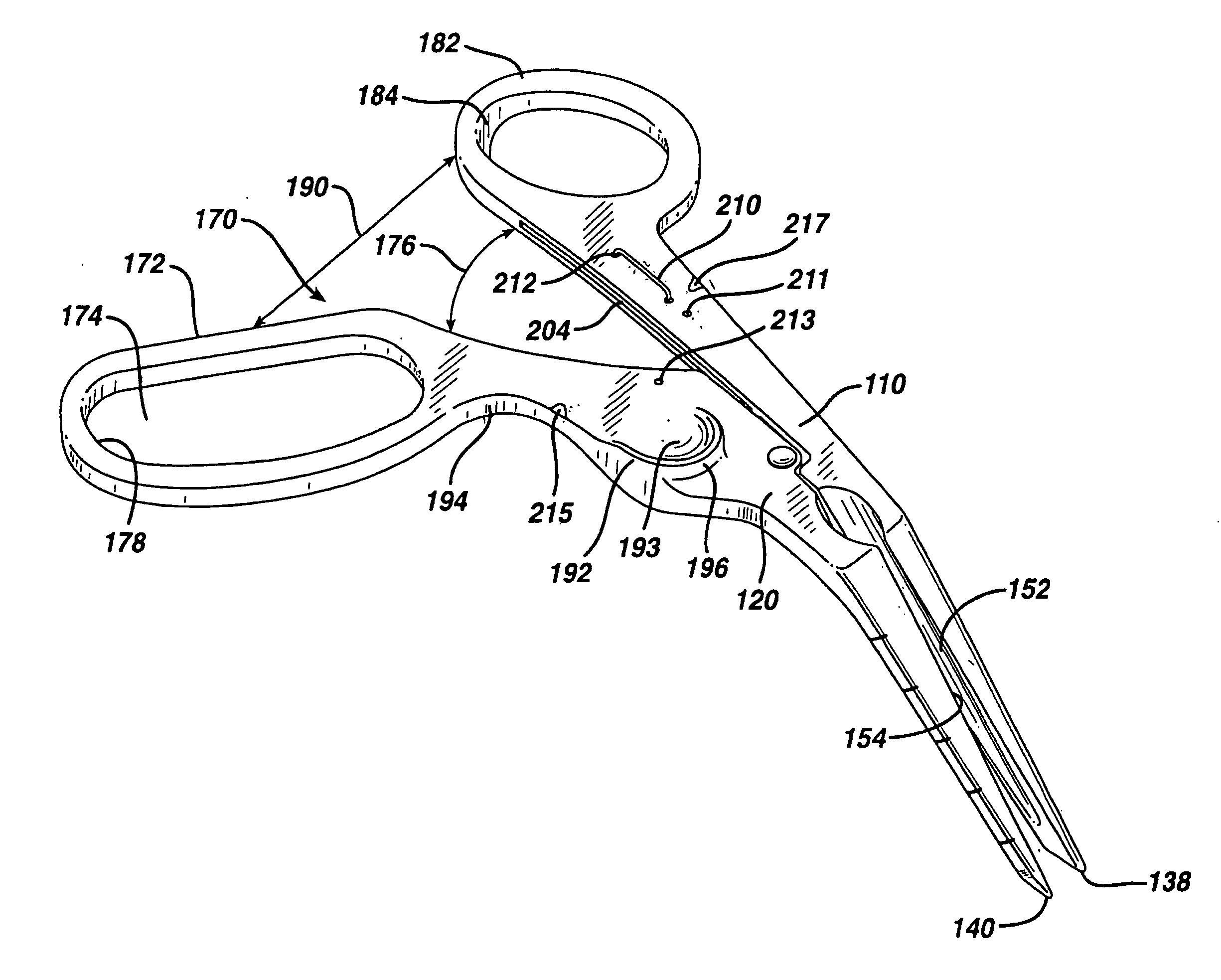
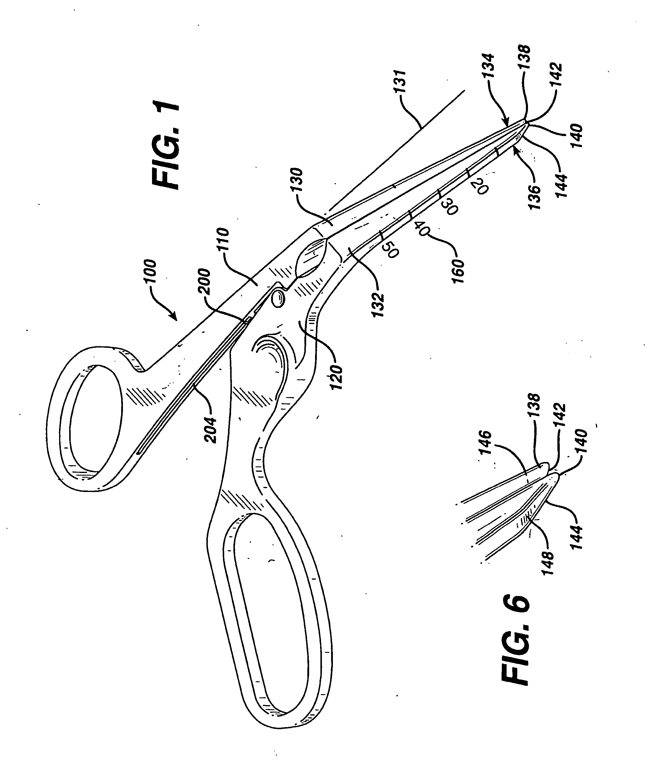
[0100] As shown in FIG. 1, a dissector / retractor tool is generally indicated at 100 and has 2 arms generally indicated at 110 and 120. The arms end in fingers 130 and 132 which are bent from the plane of the arms at an angle 131 of anywhere from 20 degrees to 80 degrees but preferably from 30 degrees to 45 degrees. The ends of the fingers 134 and 136, respectively on fingers 130 and 132 have points 138 and 140 which are pointed but not sharp and not rounded. The points are chamfered at the bottoms 142 and 144, respectively. The chamfer provides an angle which is supplementary to the angle of the fingers to provide a flat plane with the horizontal. Chines on the flat plane at the outside lower leading surface of the fingertips 146 and 148, respectively provide for a sharp bottom when the dissecting fingers are acting together.

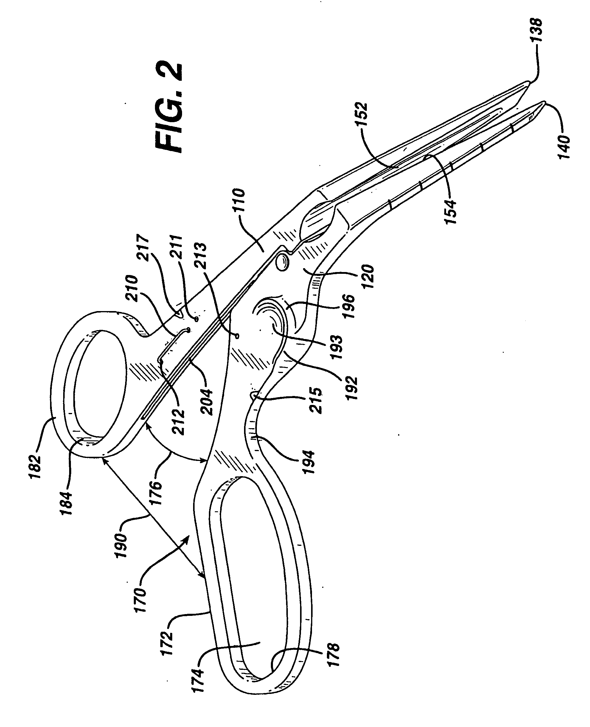
[0101] As shown in FIG. 2, moving the arms of the dissector-retractor together will spread the fingers. The fingers of the dissector-retractor, as shown in FIG...


PUM


Abstract

A tubular conduit is used to access blood vessels or other structures in the human body. The conduit has a distal tip angled to match the angle of entry into the body and an end contour adapted for the surface of the target vessel or organ. The contour may be curved to match the curve on the outer surface of the vessel or organ. The conduit's angled and contoured distal end may be adapted to engage, and align the conduit with, the surface of the vessel or organ. The conduit bears a longitudinal groove along its lower, inner surface. When the conduit is appropriately aligned, the groove may be used to guide a needle tip to the desired location, for example, the mid-line of the vessel or organ.

Description

[0001] This application is a continuation of and claims the benefit of U.S. patent application Ser. No. 10 / 862,905 which is a divisional of U.S. patent application Ser. No. 10 / 030,216 (now U.S. Pat. No. 6,761,725), filed Sep. 3, 2002, which is filed under 35 U.S.C. §371 from Appl. No. PCT / US00 / 24684, filed Sep. 8, 2000, which claims the benefit of U.S. Prov. Appl. No. 60 / 152,745, filed Sep. 8, 1999. U.S. patent application Ser. No. 10 / 862,905, filed Jun. 7, 2004, is hereby incorporated by reference in its entirety.BACKGROUND OF THE INVENTION [0002] 1. Field of the Invention [0003] The present invention relates to medical procedures and instruments, and more particularly to apparatus and methods for dissection of tissue from skin to an underlying blood vessel or body structure, and the methods of accomplishing such dissections and arterial and venous punctures. [0004] 2. Description of the Prior Art [0005] Present surgical practice for percutaneous puncture of the femoral artery with...

Claims


Application Information

Patent Timeline
Patent Type & Authority Applications(United States)
IPC IPC(8): A61B17/3201A61B17/28A61B17/34A61B19/00
CPCA61B17/0057A61B17/02A61B17/2812A61B17/282A61B17/3403A61B17/3439A61B2019/5206A61B2017/00654A61B2017/00778A61B2017/320044A61B2017/3405A61B2019/462A61B2017/00424A61B2090/062A61B2090/306
Inventor GRAYZEL, JEFFREYGRAYZEL, JOSEPHALLEN, WILLIAMKARL, FREDBACHMAN, ALANADAMS, RAY
Owner GRAYZEL JEFFREY
Why Eureka
Try Eureka