Sucker pin bushing

a technology of injection molding and sucker pins, which is applied in the field of injection molding devices, can solve the problems of large diameter holes for the sucker pin bushing b and excess work for the mold engineer, and achieve the effect of reducing or eliminating the flashing around the sucker pin bushing

Active Publication Date: 2007-12-20
PROGRESSIVE COMPONENTS INT CORP
View PDF13 Cites 11 Cited by
  • Summary
  • Abstract
  • Description
  • Claims
  • Application Information

AI Technical Summary

Benefits of technology

[0009]In view of the deficiencies described above, it is an object of the present invention to provide an improved sucker pin bushing, an improved sucker pin bushing that reduces or eliminates the occurrence of flashing around the sucker pin bushing.

Problems solved by technology

A common problem in three plate molding operations is flashing, that is excess plastic material from the molding process, getting into the workings of the sucker pin 190 and sucker pin bushing 210, as well as other mold components.
The drilling operation can results in a larger diameter hole for the bushing 210 and excess work for the mold engineer.

Method used


Image

  • Sucker pin bushing
  • Sucker pin bushing
  • Sucker pin bushing

Examples


Embodiment Construction

[0018]While this invention is susceptible of embodiments in many different forms, there are shown in the drawings and will herein be described in detail, preferred embodiments of the invention with the understanding that the present disclosure is to be considered as an exemplification of the principles of the invention and is not intended to limit the broad aspect of the invention to the embodiments illustrated.

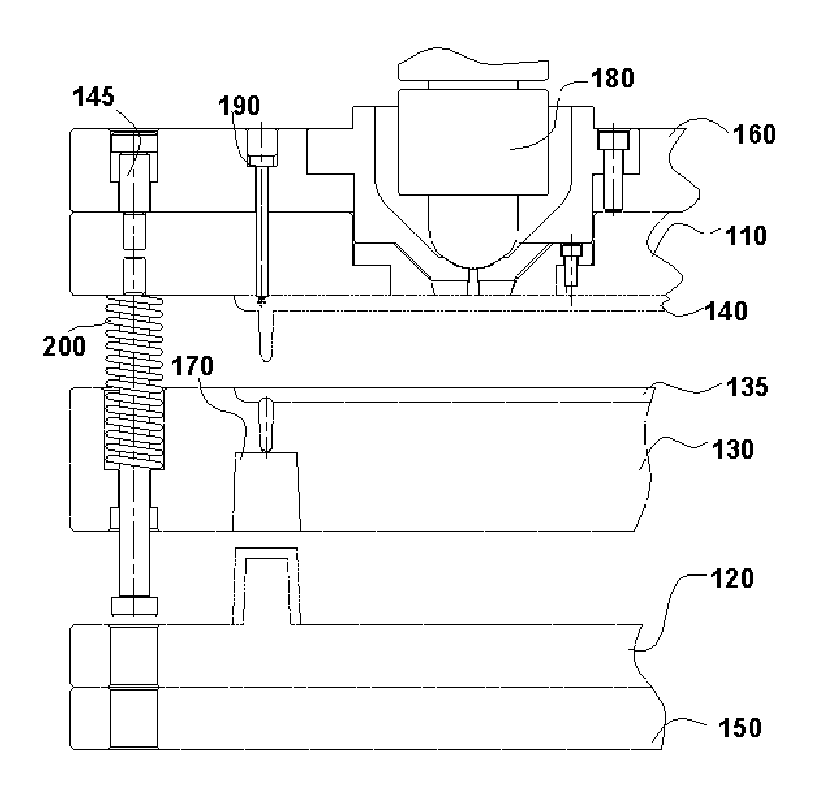
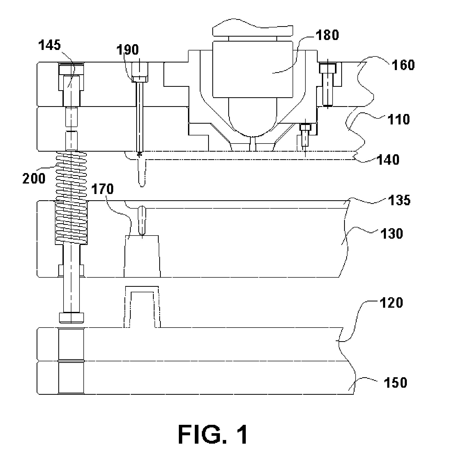
[0019]The present invention is an improved sucker pin bushing. FIG. 1 shows a sectional view of a three plate mold. The operation of the three plate mold is described above.

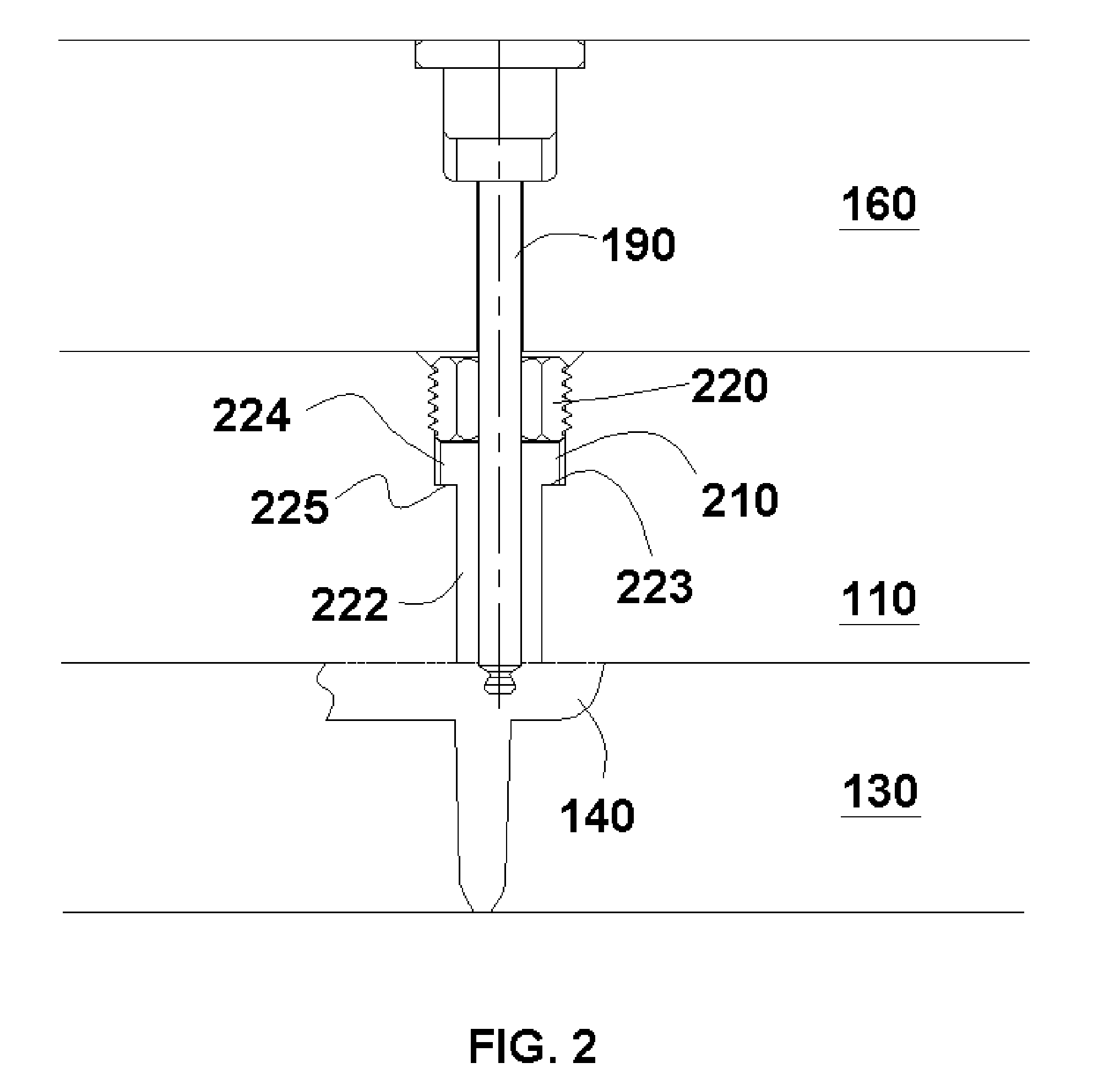
[0020]FIG. 2 shows a sectional view of a typical sucker pin and sucker pin bushing arrangement. As shown, the sucker pin 190 is secured in the top plate 160. The sucker pin 190 passes through an opening in the top plate 160 and a corresponding opening in the X plate 110. Disposed in the X plate 110, is the sucker pin bushing 210. The sucker pin 190 passes through and is coaxial with the sucker pin bushing ...


PUM

PropertyMeasurementUnit
diameteraaaaaaaaaa
compression forceaaaaaaaaaa
forceaaaaaaaaaa

Abstract

An improved sucker pin bushing for an injection mold is disclosed. In various preferred embodiments, the improved sucker pin bushing maintains much of the configuration of a conventional sucker pin bushing, namely a body portion and a head portion having a larger diameter than the body portion. A shoulder is formed where the body portion meets the head portion. However, the need for a jam screw or other retaining means is eliminated by the present invention by the inclusion of threads on the head portion of the bushing.

Description

CROSS-REFERENCE TO RELATED APPLICATION[0001]This application claims the benefit of U.S. Provisional Application No. 60 / 767,544, filed on Jun. 14, 2006, which is hereby incorporated by reference in its entirety.BACKGROUND OF THE INVENTION[0002]The present invention relates to injection molding devices, and more specifically to a sucker pin bushing of a multiple plate injection mold.DESCRIPTION OF THE RELATED ART[0003]In numerous injection molding applications, it is desirable to utilize molds with multiple plates. In a typical three-plate injection molding machine, as the name implies, there are three plates involved in the molding operation. FIG. 1 shows a sectional view of a three plate mold as described in herein. Typically these plates are referred to as the X plate 110, the B plate 120, and the A plate 130. A mold pattern 170 is formed between a portion of the B plate 120 and the A plate 130. A runner pattern 135 is formed on the A plate 130 which faces the X plate 110. The B pl...

Claims


Application Information

Patent Timeline
Patent Type & Authority Applications(United States)
IPC IPC(8): B29C45/40B29C45/00
CPCB29C45/17B29C45/2602B29K2101/12B29C2045/388B29C45/38
Inventor CERNIGLIA, ANTHONY J.
Owner PROGRESSIVE COMPONENTS INT CORP
Why Eureka
Try Eureka