Pinch valve

a technology of pinch valve and valve body, applied in the direction of diaphragm valve, valve arrangement, engine diaphragm, etc., can solve the problems of difficult or impossible to adequately clean and disinfect without disassembly, and the tubular element is also subject to earlier failure, so as to reduce or eliminate the occurrence of stretching or deformation

Active Publication Date: 2021-02-02
CHRISTINE L JEEP TRUSTEE OF THE LOUIS & PATRICIA MUELLER FAMILY TRUST DATED APRIL 2ND 2020
View PDF19 Cites 0 Cited by
  • Summary
  • Abstract
  • Description
  • Claims
  • Application Information

AI Technical Summary

Benefits of technology

[0009]What is disclosed is a pinch valve that overcomes one or more of the shortcomings and limitations set forth above, particularly, that provides effective closure under higher pressure conditions without damaging or shortening the life of the tubular element and trapping fluids, and that reduces or eliminates occurrence of stretching or deformation in a manner to harbor contaminants.
[0010]According to a preferred aspect of the invention, the valve includes a valve member that moves a pinch head laterally into a main passage of a housing or body of the valve containing the tubular element, to initially deform the tubular element from its original or free state sectional shape, e.g., round, oval, elliptical, polygonal, etc., into a generally crescent or similar shape to reduce and / or regulate flow, and then with further movement of the valve member, to deform into a generally U-shape to close and prevent flow. The pinch head preferably has a sectional shape generally the same as but a predetermined amount smaller than, an opposing inner surface bounding the main passage, and lateral or side surfaces that trail the tip or leading end of the pinch head and cooperate with opposing portions of the inner surface, to bend or fold over lateral end portions of the tubular element, that is, the opposite distal ends or legs of the U-shape. The valve member additionally includes associated laterally positioned elements, preferably in the form of pinch shoulders laterally of or adjacent to the sides of the pinch head, positioned in opposing relation to surface portions of the body or housing of the valve, and that also trail the tip or leading end of the pinch head, to contain or enclose and finally pinch the folded over lateral portions closed as the U-shape main portion of the tubular element is pinched closed, to completely prevent flow through the tubular element.
[0011]As an attendant advantage, the pinching elements are preferably configured such that as the tubular element is finally fully pinched closed, any remaining fluid between the portions being pinched together is forced out, e.g. by a squeezing or squeegeeing action, so as not to be trapped and stress the sidewall of the tubular element, even at higher pressures, e.g., greater than 40 psi but less than 125 psi and the like, and at lower temperatures, such as when carrying chilled process chemicals, spirits, etc, or when used in an outdoor or refrigerated environment. To facilitate this effect, the pinch head is preferably elongate in the flow direction and has a generally convergingly tapered or oval profile shape e.g., a boat or canoe hull profile shape when viewed in the flow direction, with no cavities or other shapes along the length thereof operable to trap and retain fluid between the pinched together sections of the tubular element.
[0012]According to another preferred aspect of the invention, the pinch shoulders and associated opposing surface portions can be angularly oriented in relation to a direction of movement of the valve member, as a non-limiting example, at between about a 20 degree and a 90 degree angle thereto. This can be desirable and advantageous, as the bent or folded over end portions of the tubular element that form the distal ends of the U-shape tend to form a loop at the very end, and this angularity and other shapes has been found to facilitate the smooth pinching together of the folded over portions in a manner to eliminate gaps and pockets that can trap fluid to deform, stretch, and / or weaken or perforate the sidewall. The pinch shoulders and associated adjacent sides of the pinch head can also be advantageously shaped, e.g., convex, concave, etc., and the opposing inner surfaces of the valve housing and side surfaces generally matingly shaped, e.g., concave, convex, etc., in a manner such that the folded together ends of the tubular element are pinched to remove any gaps and / or pockets.
[0013]According to another preferred aspect of the invention, the pinch head is elongate in the direction of flow through the tubular element, as a non-limiting example, from about 1.5 to several times the lateral extent of width of the tubular element, so as to pinch the tubular element three dimensionally, which has been found to reduce potential for leakage and also stress concentrations. Also preferably, the pinch head is sufficiently paced from connection to fittings such as barbed fittings, clamps, and the like, so that deformation of the tubular element does not form small gaps or crevices in which fluid can be trapped so as to become contaminants during later use.

Problems solved by technology

The tubular element is also subject to earlier failure due to the higher pinching force required.
As another observed shortcoming of several known pinch valves wherein one or both ends of the tubular element attaches to a coupling via frictional fit, e.g., using one or more barbs, it has been found that the closing action of the valve or pinch member can stretch or deform the tubular element past its elastic limit so as to form a small cavity between the tubular element and the coupling that can collect and trap fluid in which contaminants such as bacteria and / or fungus can grow, and which can be difficult or impossible to adequately clean and disinfect without disassembly.

Method used


Image

  • Pinch valve
  • Pinch valve
  • Pinch valve

Examples


Embodiment Construction

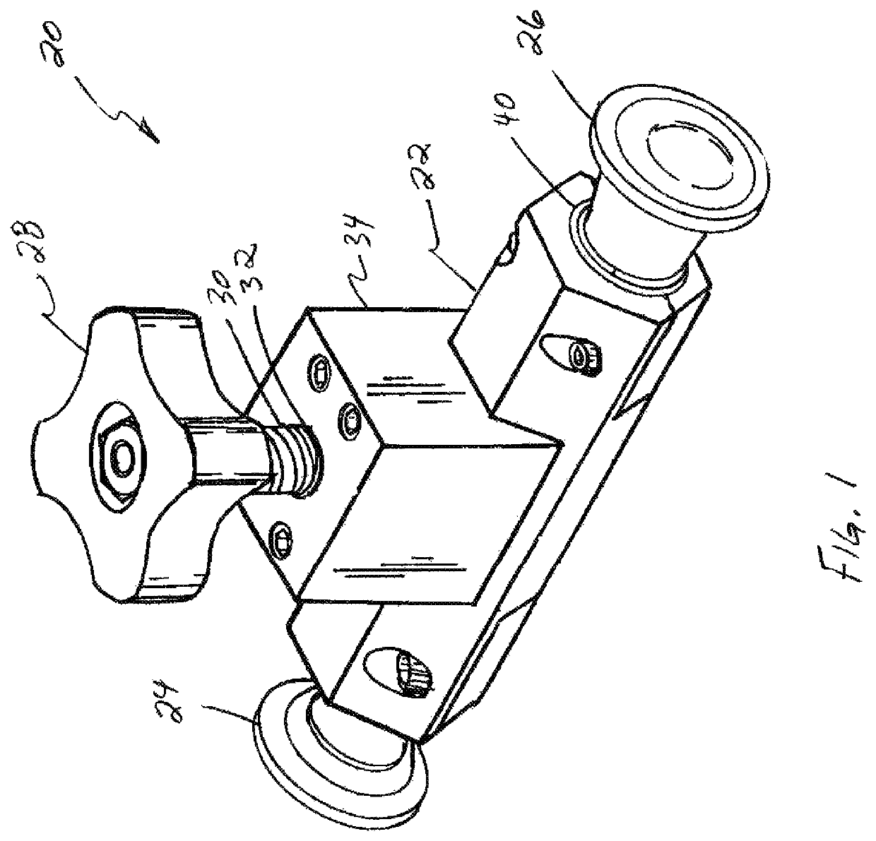
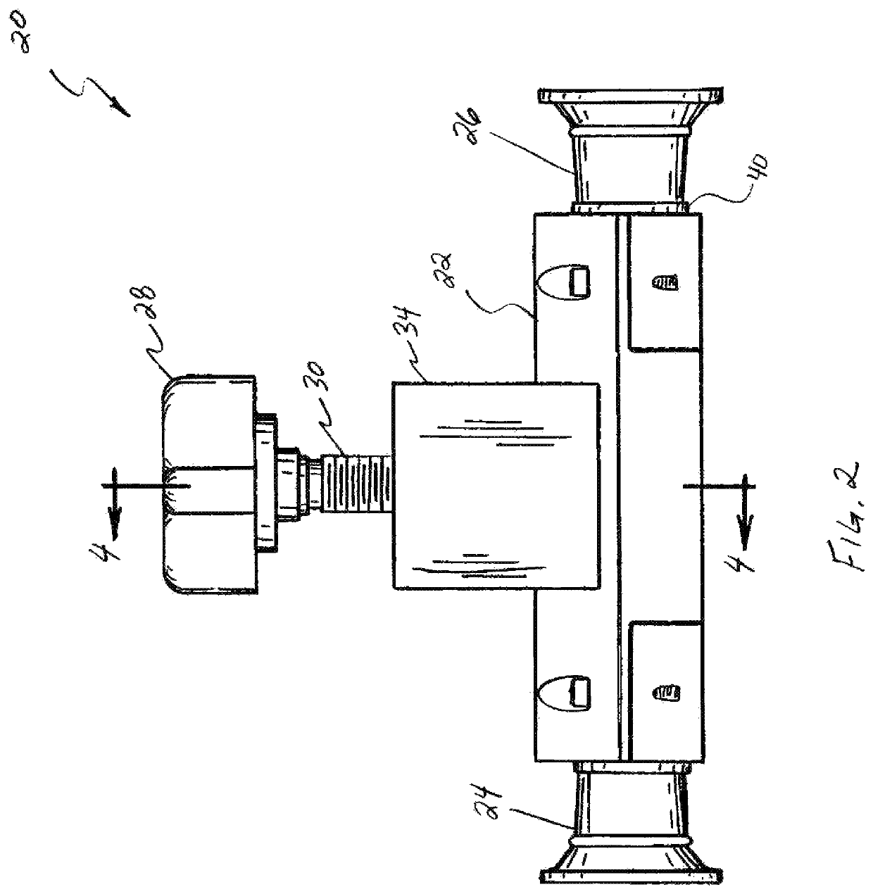
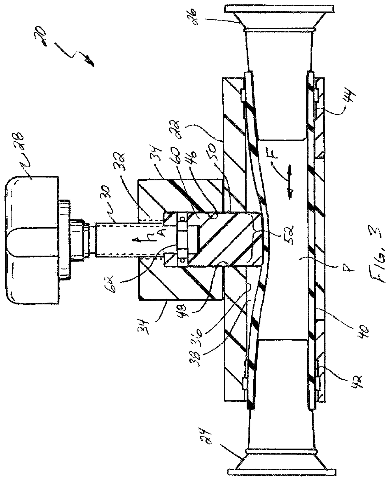
[0031]Referring now to the drawings, in FIGS. 1-9 a pinch valve 20 constructed and operable according to the teachings of the present invention is shown. Valve 20 includes a valve body 22 that is hollow and open on opposite ends to accommodate fittings 24 and 26 for attachment in fluid connection to a fluid system, such as tubes or hoses, in the well known manner, for flow of the fluid through valve body 22, also in the well known manner. A handle 28 external to valve body 22, connects to a threaded shaft 30 that extends into a threaded aperture 32 in a valve block 34 affixed to and forming a part of valve body 22. All of the above described elements can be fabricated from suitable rigid material such as a metal or plastics, in the well known manner.

[0032]Valve body 22 is a hollow, open ended structure including an inner surface 36 bounding and defining an open ended main passage 38 extending therethrough. A resiliently flexible, hollow tubular element 40 occupies passage 38, and ha...


PUM


Abstract

The pinch valve includes a valve member movable to compress or pinch a resilient tubular element extending through a passage of a housing or body of the valve to varying extents to regulate or prevent fluid flow through the tubular element. The valve member includes a valve head configured to pinch the tubular element through a range of progressively more flow restrictive crescent shapes into a generally U-shape, and while doing so cooperates with side surfaces of the body or housing to bend or fold over lateral end portions of the tubular element that form distal ends of the U-shape. The valve member additionally includes pinch shoulders that follow the pinch head and secondarily pinch or compress the folded over end portions together to complete closure of the tubular element as the U-shape is pinched closed, to prevent leaking, trapping of fluids, and damaging the tubular element under high fluid pressures.

Description

[0001]This application claims the benefit of U.S. Provisional Application No. 62 / 303,161, filed Mar. 3, 2016.TECHNICAL FIELD[0002]This invention relates generally to a pinch valve including a valve member movable to compress or pinch a resilient tubular element extending through a passage of a housing or body of the valve to regulate or prevent fluid flow through the tubular element, and more particularly, that pinches the tubular element through a range of generally crescent shapes into a generally U-shape, and in doing so brings together and bends or folds over opposite lateral end portions of the tubular element that form the distal ends of the U-shape, respectively, then pinches them closed as the U-shape portion is pinched closed, to complete closure and prevent leaking, trapping of fluids, and damaging the tubular element under high fluid pressures.BACKGROUND ART[0003]U.S. Provisional Application No. 62 / 303,161, filed Mar. 3, 2016, is incorporated herein by reference in its en...

Claims


Application Information

Patent Timeline
Patent Type & Authority Patents(United States)
IPC IPC(8): F16K7/06
CPCF16K7/061
Inventor MUELLER, LOUIS E.
Owner CHRISTINE L JEEP TRUSTEE OF THE LOUIS & PATRICIA MUELLER FAMILY TRUST DATED APRIL 2ND 2020
Why Eureka
Try Eureka