Effects pedal retaining unit and pedal board system

a technology of effect pedals and retaining units, applied in the field of musical instrument effects pedals and pedal boards, can solve the problems of depreciation of pedal value upon resale, damage to valuable pedals, and difficulty in removal of adhesive substances, and achieve the effect of stabilizing a musical effects pedal

Inactive Publication Date: 2007-12-27
COLLINS SR MAX
View PDF9 Cites 36 Cited by
  • Summary
  • Abstract
  • Description
  • Claims
  • Application Information

AI Technical Summary

Benefits of technology

[0011]It is yet another object of the present application to provide a musical effects pedal retaining unit that stabilizes a musical effects pedal during use more effectively than existing technologies.
[0012]It is yet another object of the present application to provide a musical effects pedal retaining unit which stabilizes a musical effects pedal without requiring application of adhesive directly to the musical effects pedal.

Problems solved by technology

A problem arises however, in that musicians seek to preserve the condition, and thus the value, of their pedals while at the same time utilizing them musically.
A prominent type of damage to valuable pedals occurs when musicians attempt to stabilize them to their “pedal boards,” a device by which pedals are grouped together to allow for easier access when playing (See FIG. 7).
However, in order to adhere one side of such a fabric hook and loop fastener system to the pedal, a person must subject his or her valuable pedal to the sticky, corrosive substance present on the adhesive side of the system.
This adhesive substance is extremely difficult to remove and greatly depreciates the value of the pedal upon resale.
There are a variety of pedal boards on the market and disclosed in the prior art, however, none accomplish the benefits of the various embodiments disclosed herein by Applicant.
All of these pedal boards are designed to accommodate multiple pedals and all use fabric hook-and-loop fasteners to stabilize the pedal with reference to the pedal board, however, none of these references adequately protect or preserve the pedals being used to a degree desired by typical collectors.
U.S. Pat. No. 5,866,829, to Pecororao (1999) and U.S. Pat. No. 6,538,185 to Stratton (2003) both disclose pedal rack systems, but neither of the technologies appear to solve the problems addressed by the present application.
Thus, the primary shortcoming of these devices, and a primary problem that that Applicant seeks to remedy, is the necessity of applying damaging adhesive to the surface of valuable effects pedals.

Method used


Image

  • Effects pedal retaining unit and pedal board system
  • Effects pedal retaining unit and pedal board system
  • Effects pedal retaining unit and pedal board system

Examples


Embodiment Construction

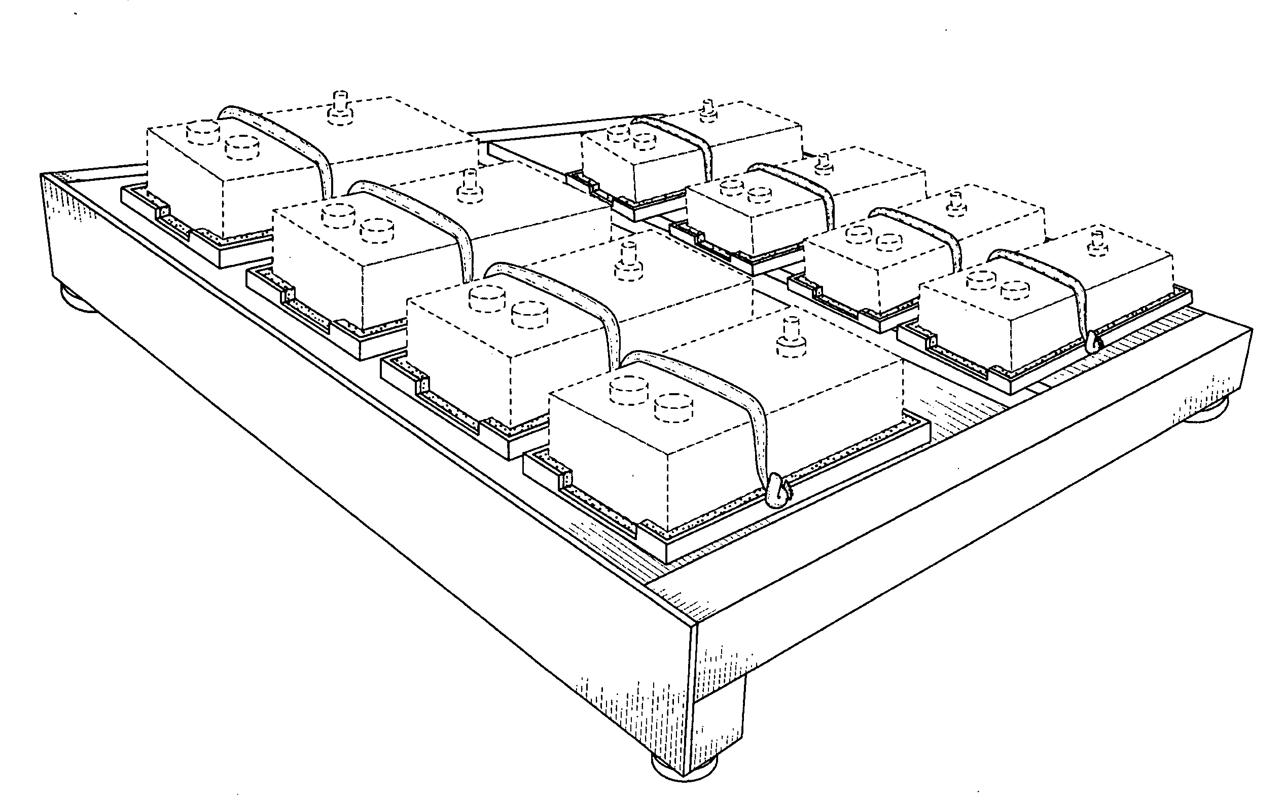
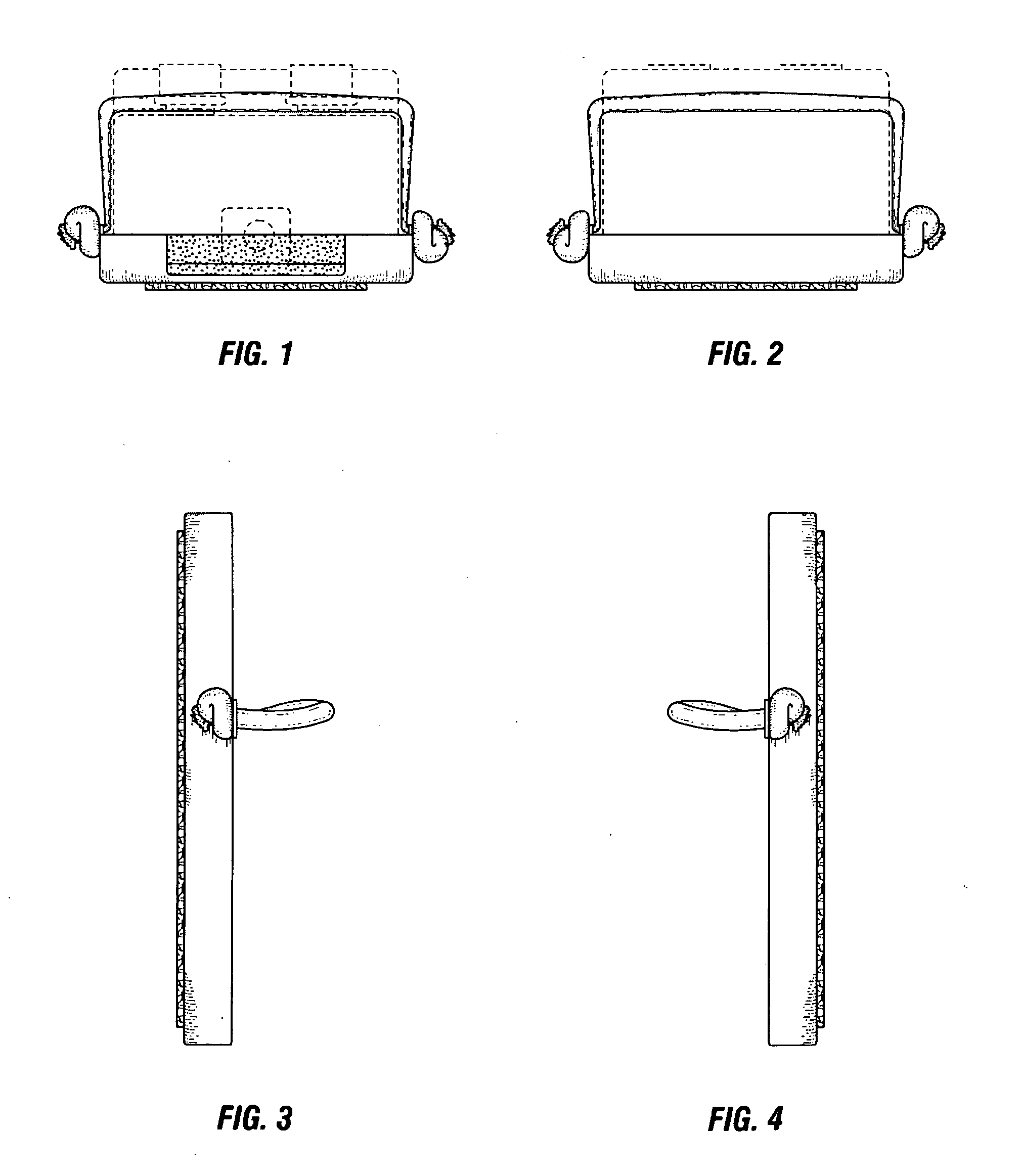
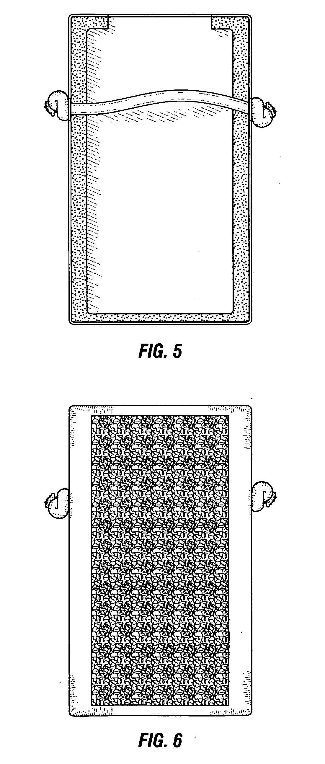
[0023]FIG. 1 is a front perspective view of a preferable pedal retaining unit assembly 1. Basic components of the shown pedal retaining assembly 1 comprise a retaining body 2 with a preferable accommodation bracket 7, and an attachment surface 6. A preferable mode of use is that an effects pedal is removably placed in the retaining body 2 and stabilized via the retaining means 4. Power supply and other electrical cables to the pedals typically are fixed through the accommodation bracket 7. The pedal retaining unit 1 and pedal may then be placed as a whole and fastened at a desired location to a pedal board, preferably by an attachment surface 6 fixedly disposed on an underside of said retaining body 2. Thus, a user can properly locate and stabilize an effect pedal to a pedal board without resorting to the use of adhesives that damage the pedals. Applicant has found that the retaining body 2 may be fashioned from any rigid or semi-rigid material, such as any variety of metal or plast...


PUM


Abstract

A musical effects pedal retaining unit comprising a retaining body, a retaining means affixed to said retaining body by retaining means connectors and an attachment surface fixed to said retaining body. This pedal retaining unit is preferably used with a pedal board system to secure at least one musical effect pedal while simultaneously preserving the effects pedal.

Description

CROSS-REFERENCE TO RELATED APPLICATIONS[0001]Not applicable.STATEMENT REGARDING FEDERALLY SPONSORED RESEARCH OR DEVELOPMENT[0002]Not applicable.BACKGROUND OF THE INVENTION[0003]1. Field of Invention[0004]The present application relates to the field of musical instrument effects pedals and pedal boards.[0005]2. Background of the Invention[0006]A musical instrument effects pedal is a small device inserted into the signal path, between the instrument and the amplification unit, of electrical musical instruments in order to alter the sound quality of the signal. The musician switches between the “clean” or unaltered sound, and the “affected” sound by activating a switch with his or her foot—thus the “pedal” nomenclature. Effects pedals have been widely used since the 1960's, and a lucrative niche market has arisen for the resale of highly sought-after vintage pedals. A problem arises however, in that musicians seek to preserve the condition, and thus the value, of their pedals while at ...

Claims


Application Information

Patent Timeline
Patent Type & Authority Applications(United States)
IPC IPC(8): G10D13/02
CPCG10H1/32
Inventor COLLINS, MAX
Owner COLLINS SR MAX
Why Eureka
Try Eureka