Increase gray scales of projection system by reflecting light from mirror elements with non-uniform intensity distribution

a technology of projection system and mirror element, applied in the field of image display system, can solve the problem of adding gray scale, and achieve the effect of low operational voltage and flexible control of gray scale of display

Inactive Publication Date: 2007-12-27
SILICON QUEST KABUSHIKI KAISHA +1
View PDF3 Cites 9 Cited by
  • Summary
  • Abstract
  • Description
  • Claims
  • Application Information

AI Technical Summary

Benefits of technology

[0015]One aspect of the present invention relates to the control of a light source to project an incident light with a predefined unsymmetrical distribution of light intensity in the incident light flux. The purpose of controlling the intensity with unsymmetrical distribution of the incident light is to apply such distribution in coordination with the spatial light modulators (SLMs) that has intermediate state control for providing more flexibly controllable gray scales of display. The control and generation of display of additional gray scales are achieved without requiring a higher speed of micromirror oscillation thus maintaining a low operational voltage.
[0017]In yet another aspect, the present invention provides a projection system by projecting a non-uniform and non-symmetrical incident light that has variety of shapes of incident light cross section at the pupil along an optical path. By more precisely controlling the intensity distribution or the cross section shapes of the incident light, the gray scale for display is now controllable to project finer scale of brightness differences between adjacent pixels with an additional controllable state to provide a fraction of brightness of the fully-on state for display. The annoying artifacts shown on a display caused by adjacent pixels having huge gray scale gaps can be significantly reduced.
[0018]In yet another aspect, the present invention provides a method of controlling the shapes and the intensity distribution of the incident light by providing intermediate states not only between the ON and OFF states but also other directions. The system can establish variety of intermediate areas in different diffraction areas. Furthermore, the method includes a step of coordinating the color filters or color wheels and intensity distribution of the incident light with an array of micromirror devices. Optionally, the micromirrors are enabled to oscillate in a reverse direction or stop before the micromirror completes a full oscillation cycle. Aided by such control flexibility and the fractional brightness for image display during an intermediate oscillation state, additional flexibilities are now provided to fine tune the gray scale for each image pixel especially for the high brightness display area where a gray scale difference are proportionally amplified due to the high intensity of light projections.
[0020]It is another aspect of this invention that the contrast is improved by minimizing the light flux at OFF time to achieve high gray scale. If the deflection angle close to OFF is used, the contrast is worsened and high gray scale cannot be obtained. This invention solves these problems and is the intermediate gray scale generating apparatus utilizing light modulation to achieve high gray scale.

Problems solved by technology

With an incident light that has a non-uniform intensity distribution when projecting onto the SLM, additional gray scales can be generated because the projected image on a screen is not an uniform image.

Method used


Image

  • Increase gray scales of projection system by reflecting light from mirror elements with non-uniform intensity distribution
  • Increase gray scales of projection system by reflecting light from mirror elements with non-uniform intensity distribution
  • Increase gray scales of projection system by reflecting light from mirror elements with non-uniform intensity distribution

Examples


first embodiment

[0041]A description will first be made of the basic configuration of the projection system according to a first embodiment of the invention with reference to FIGS. 2 and 3.

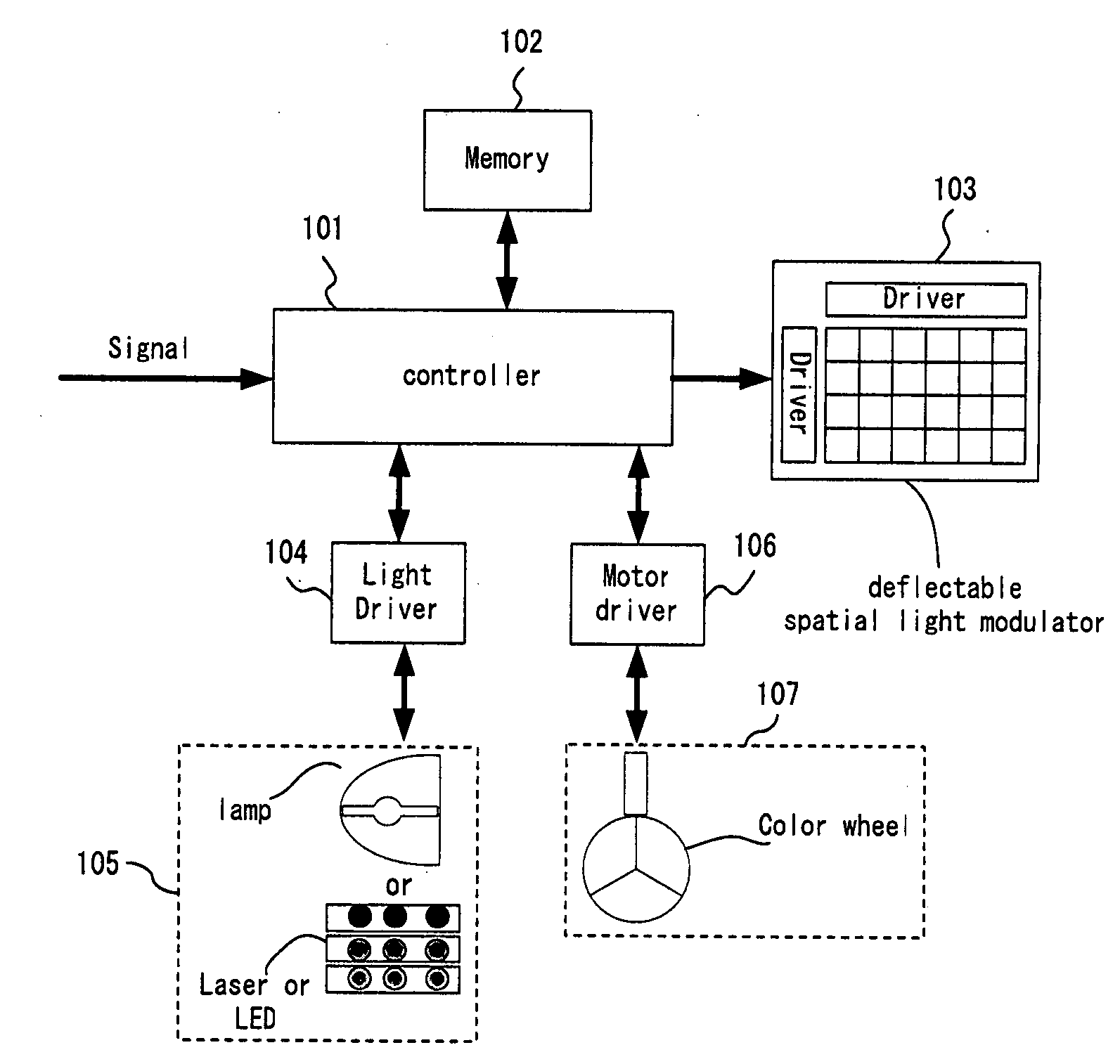
[0042]FIG. 2 is a system diagram of the projection system according to this embodiment. The projection system projects images on a screen or other kinds of display surface (not shown) according to image signals inputted to a controller 101. The controller further accesses data stored in a memory 102 for controlling a deflectable spatial light modulator (hereinafter simply referred to as “SLM”) 103. The controller 101 further controls a light driver 104 that receives an incident light from a light source 105. The projection system may further include a motor driver 106 to drive a color wheel included in a filter unit 107 in order to display color images.

[0043]The controller 101 controls the SLM 103 and the drivers 104, 106 to project an image according to an input image signal. The memory 102 stores data necessary ...

second embodiment

[0061]The projection system according to a second embodiment of the invention is a system in which the direction of the optical axis of the Intermediate light is limited. Other than the limited range of optical axis direction, the key configuration of the projection system according to the second embodiment is the same as that of the projection system according to the first embodiment described above.

[0062]The projection system according to this embodiment is configured such that for each of the deflectable spatial light modulating elements in the SLM 103. The optical axis of the Intermediate light lies in the space between two planes inclined ±15 degrees to the plane A including the optical axis of the light originating from the light source 105 and incident on the mirror plate and the optical axis of the OFF light. The plane A and the two planes having an incline angle of ±15 degrees relative to the plane A intersect on the reflection plane of the mirror plate.

[0063]FIGS. 5A to 5E...

third embodiment

[0078]The projection system according to a third embodiment of the invention is a system in which the direction of the optical axis of the Intermediate light is limited within a range that is different from the projection system according to the second embodiment described above. The key configuration of the projection system according to the third embodiment is the same as that of the projection system according to the first embodiment described above.

[0079]The projection system according to this embodiment is configured such that in each of the deflectable spatial light modulating elements in the SLM 103, the optical axis of the Intermediate light lies in a cone. the center axis of rotation of the cone is a normal to the deflectable spatial light modulating element. The curved surface of the cone includes the optical axis of the OFF light. The projection system according to this embodiment includes two light sources. The light source is configured such that the light beams from th...


PUM


Abstract

Additional control flexibilities to generate more gray scales for an image display system is achieved by controlling the intensity distribution of the light projection from a light source to a deflecting mirror to further coordinate with the control of the intermediate states of the deflecting mirror. The control light source intensity distribution can provide incident light with wide varieties of intensity distributions including non-uniform, symmetrical and non-symmetrical, different distributions of polarizations, various cross sectional shapes of the incident lights and other combinations of all of the above variations. More stable and better control of gray scale control is also achieved by optimizing the intensity distributions of the incident light to produce the best visual effects of the image display.

Description

[0001]This application is a Non-provisional application of a Provisional Application 60 / 816,452 filed on Jun. 26, 2006. The Provisional Application 60 / 816,452 is a Continuation in Part (CIP) application of a pending U.S. patent application Ser. Nos. 11 / 121,543 filed on May 4, 2005. The application Ser. No. 11 / 121,543 is a Continuation in part (CIP) application of three previously filed applications. These three applications are Ser. No. 10 / 698,620 filed on Nov. 1, 2003, Ser. No. 10 / 699,140 filed on Nov. 1, 2003, and Ser. No. 10 / 699,143 filed on Nov. 1, 2003 by one of the Applicants of this patent application. The disclosures made in these patent applications are hereby incorporated by reference in this patent application.BACKGROUND OF THE INVENTION[0002]1. Field of the Invention[0003]This invention relates to image display system. More particularly, this invention relates to display system with light source for projecting controllable non-symmetrical and non-uniform intensity distri...

Claims


Application Information

Patent Timeline
Patent Type & Authority Applications(United States)
IPC IPC(8): G03B21/26
CPCG03B21/14H04N9/3114H04N9/3197H04N9/3152H04N9/3161H04N9/312G03B21/008
Inventor ISHII, FUSAOMAEDA, YOSHIHIROICHIKAWA, HIROTOSHIARAI, KAZUMA
Owner SILICON QUEST KABUSHIKI KAISHA
Why Eureka
Try Eureka