Intensity distribution of incident light flux

a technology of incident light flux and intensity distribution, which is applied in the field of intensity distribution of incident light flux, can solve the problem of uniform projection image on the screen, and achieve the effect of low operational voltage and flexible control of gray scales of display

Inactive Publication Date: 2007-07-26
SILICON QUEST KABUSHIKI KAISHA +1
View PDF6 Cites 9 Cited by
  • Summary
  • Abstract
  • Description
  • Claims
  • Application Information

AI Technical Summary

Benefits of technology

[0013] The present invention relates to control of a light source to project an incident light with a predefined distribution of light intensity in the incident light flux. The purpose of controlling the intensity distribution of the incident light is to apply such distribution in coordination with the spatial light modulators (SLMs) that has intermediate state control for providing more flexibly controllable gray scales of display. The control and generation of display of additional gray scales are achieved without requiring a higher speed of micromirror oscillation thus maintaining a low operational voltage.
[0015] In yet another aspect, the present invention provides a projection device by projecting a non-uniform incident light or variety of shapes of incident light cross section at the pupil along an optical path. By controlling the intensity distribution or the cross section shapes of the incident light, the gray scale for display is now controllable to project finer scale of brightness differences between adjacent pixels with an additional controllable state to provide a fraction of brightness of the fully-on state for display. The annoying artifacts shown on a display caused by adjacent pixels having huge gray scale gaps can be significantly reduced.

Problems solved by technology

If the incident light is not uniform on a SLM, the projected image on a screen is not an uniform image.

Method used


Image

  • Intensity distribution of incident light flux
  • Intensity distribution of incident light flux
  • Intensity distribution of incident light flux

Examples


second embodiment

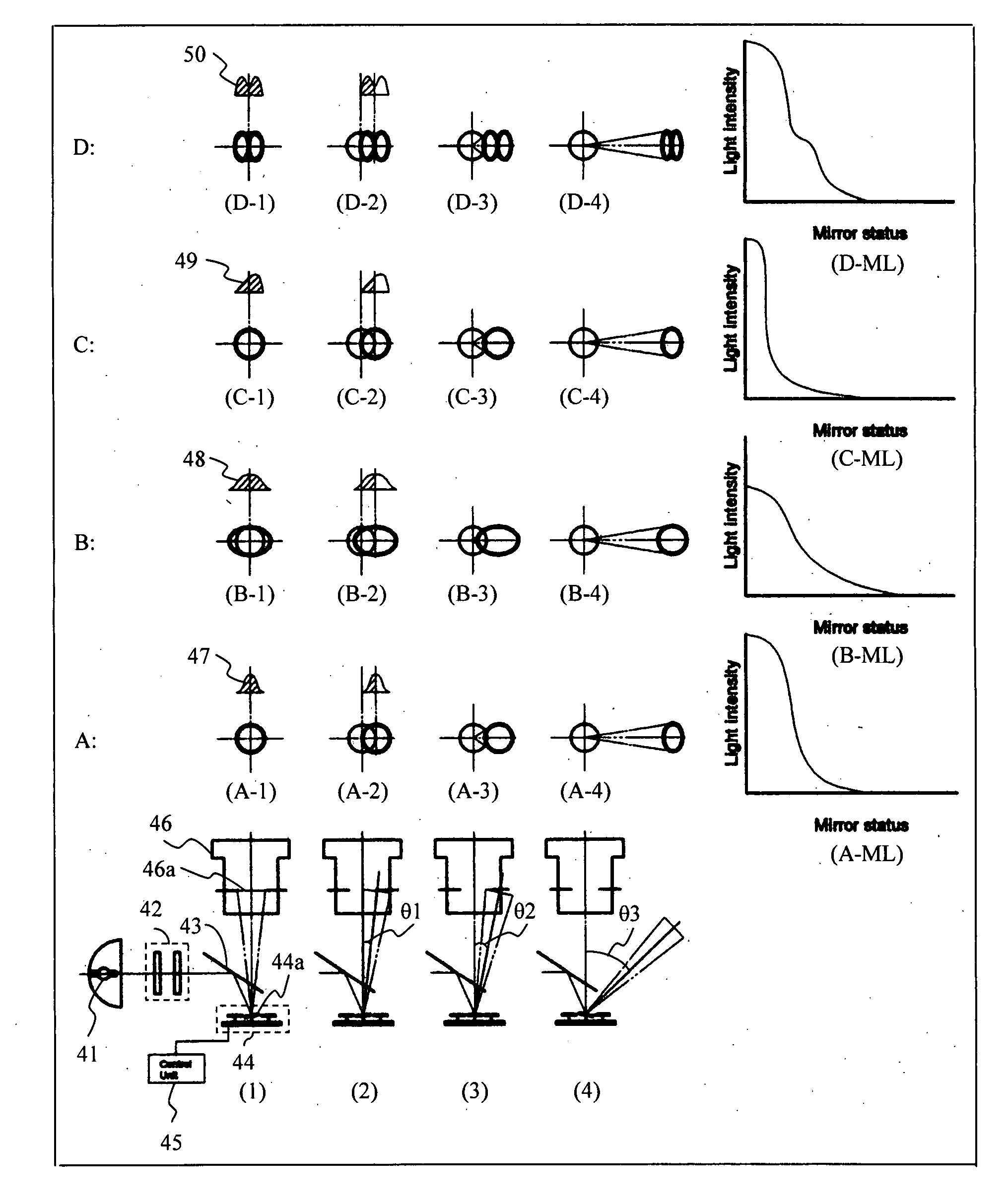
[0091] A projection device according to this embodiment comprises a light source, illumination optics means for collecting and directing light from the light source, a deflecting type spatial light modulator (hereinafter referred to simply as SLM), a projection light path for projecting the light modulated by the SLM, and control means for controlling the deflection angle holding operation and the oscillation operation of each deflecting mirror (mirror element) of the SLM based on an input signal so that a desired light amount is directed toward the optical pupil of the projection light path.

[0092] In the projection device according to this embodiment, the light source and / or the illumination optics means are configured so that the intensity distribution of illumination light in the position of the optical pupil of the projection light path becomes non-uniform. Additionally, the control means can control the deflecting mirror to hold a particular deflection angle in a first control...


PUM


Abstract

Additional control flexibilities to generate more gray scales for an image display system is achieved by controlling the intensity distribution of the light projection from a light source to a deflecting mirror to further coordinate with the control of the intermediate states of the deflecting mirror. The control light source intensity distribution can provide incident light with wide varieties of intensity distributions including non-uniform, symmetrical and non-symmetrical, different distributions of polarizations, various cross sectional shapes of the incident lights and other combinations of all of the above variations. More stable and better control of gray scale control is also achieved by optimizing the intensity distributions of the incident light to produce the best visual effects of the image display.

Description

[0001] This application is a Continuation in Part (CIP) Application of pending U.S. patent application Ser. Nos. 11 / 121,543 filed on May 3, 2005. The application Ser. No. 11 / 121,543 is a Continuation in part (CIP) Application of three previously filed Applications. These Three Applications are 10 / 698,620 filed on Nov. 1, 2003,10 / 699,140 filed on Nov. 1, 2003, and Ser. No. 10 / 699,143 filed on Nov. 1, 2003 by the applicant of this patent applications. The disclosures made in these patent applications are hereby incorporated by reference in this patent application.TECHNICAL FIELD [0002] This invention relates to image display system. More particularly, this invention relates to display system with light source for projecting controllable intensity distribution of incident light flux for controlling gray scales of image display. BACKGROUND OF THE INVENTION [0003] Even though there are significant advances made in recent years on the technologies of implementing electromechanical micromi...

Claims


Application Information

Patent Timeline
Patent Type & Authority Applications(United States)
IPC IPC(8): G02B26/00G02B26/08
CPCG02B26/0841G02B27/09G03B21/14G09G3/2011H04N9/3197H04N5/7458H04N9/3114H04N9/3155G09G3/346G03B21/008
Inventor ISHII, FUSAOMAEDA, YOSHIHIROICHIKAWA, HIROTOSHIARAI, KAZUMA
Owner SILICON QUEST KABUSHIKI KAISHA
Why Eureka
Try Eureka