Control of micromirrors with intermediate states

a control circuit and micromirror technology, applied in the field of micromirror arrays and control circuits to control the micromirrors, can solve the problems of imposing limitations on the quality of the display, adverse effects on image quality, and limitations of the use of high-quality images, so as to achieve more flexible control of the gray scale of the display and low operation voltage

Active Publication Date: 2005-09-22
IGNITE INC
View PDF2 Cites 31 Cited by
  • Summary
  • Abstract
  • Description
  • Claims
  • Application Information

AI Technical Summary

Benefits of technology

[0012] The present invention relates to control circuits for micromirror devices and arrays of micromirror devices. The purpose of controlling the arrays is to apply such array as spatial light modulators (SLMs). In one aspect, the present invention provides a micromirror device in which the reflecting element is controlled to reflect light for image display at multiple intermediate positions for providing more flexibly controllable gray scales of display without requiring a higher speed of micromirror oscillation thus maintaining a low operational voltage.

Problems solved by technology

Even though there are significant advances made in recent years on the technologies of implementing electromechanical micromirror devices as spatial light modulator, there are still limitations and difficulties when employed to provide high quality images display.
Specifically, when the display images are digitally controlled, the image qualities are adversely affected due to the fact that the image is not displayed with sufficient number of gray scales.
The on-and-off states of micromirror control scheme as that implemented in the Patent 5,214,420 and by most of the conventional display system imposes a limitation on the quality of the display.
Specifically, when applying conventional configuration of control circuit has a limitation that the gray scale of conventional system (PWM between ON and OFF states) is limited by the LSB (least significant bit, or the least pulse width).
Due to the On-Off states implemented in the conventional systems, there is no way to provide shorter pulse width than LSB.
The limited gray scales lead to degradations of image display.
That leads to image degradations.
The artifacts are generated due to a technical limitation that the digital controlled display does not provide sufficient gray scales.
The micromirrors manufacture by applying the CMOS technologies probably would not be suitable for operation at such higher range of voltages and therefore the DMOS micromirror devices may be required.
In order to achieve higher degree of gray scale control, a more complicate manufacturing process and larger device areas are necessary when DMOS micromirror is implemented.
Conventional modes of micromirror control are therefore facing a technical challenge that the gray scale accuracy has to be sacrificed for the benefits of smaller and more cost effective micromirror display due to the operational voltage limitations.
However, these inventions have not addressed and provided direct resolutions for a person of ordinary skill in the art to overcome the above-discussed limitations and difficulties.

Method used


Image

  • Control of micromirrors with intermediate states
  • Control of micromirrors with intermediate states
  • Control of micromirrors with intermediate states

Examples


Embodiment Construction

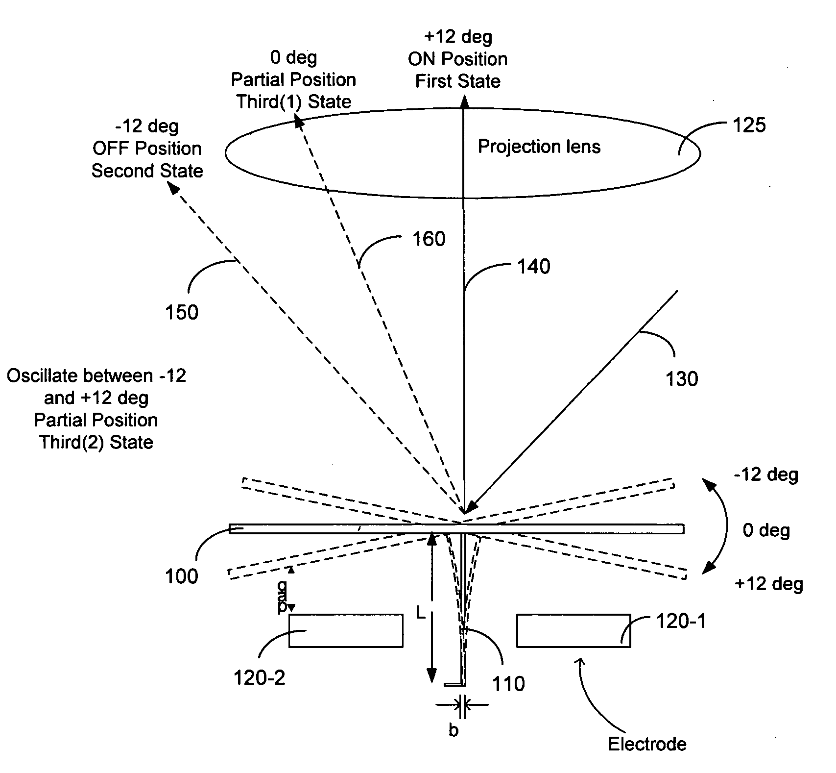
[0029] Referring to FIG. 2 for a side cross sectional view for illustrating the oscillating motions of a micromirrors according to the control circuit of the present invention. A micromirror 100 supported on a hinge 110 formed on a substrate (not shown), is electrically controlled by two electrodes 120-1 and 120-2 to move to different positions, e.g., from +12 degrees to −12 degrees as shown. The incident light is projected along an optical path 130 and the light reflected from the micromirror 100 is projected to a projection lens 125 for further projecting to a display surface (not shown). The mirror surface is multi-layer to achieve higher reflection. An Aluminum surface can provide 90-92% reflectance but multi-layer can provide a higher reflection up to 98%. The micromirror is controlled to move to a full-on state when the micromirror is positioned at the +12 degrees with the reflected light projected fully onto the projection lens along a 140 direction perpendicular to the proje...


PUM


Abstract

A micromirror device with at least one intermediate state is disclosed in this invention with the reflecting mirror placed at an angular position between a fully on angle and fully off angle. The micromirror device includes a reflecting element supported on a hinge for oscillating and positioning at least three angular positions. The micromirror device further has a control circuit for receiving a series of control words of different number of bits as a time modulation signal to control the reflecting element for controlling a gray scale of display wherein the control circuit further receiving an oscillation signal for superimposing on the time modulation signal for oscillating the reflecting element for further controlling the gray scale of display. The series of control words further includes a sequence of control words of a least number of bits to a maximum number of bits of a least number of bits to a maximum number of bits with a time gap between each of the control words. The oscillating signal may be inserted optionally into a gap between the control words, into every control word, into a control word of the MSB, or into a control word of the LSB, In a preferred embodiment, the oscillating signal is applied to dispose the reflecting element at an intermediate state with a zero degree relative to an incident light.

Description

[0001] This application is a Continuation in Part (CIP) Application of pending U.S. patent application Ser. Nos. 10 / 698,620 filed on Nov. 1, 2003,10 / 699,140 filed on Nov. 1, 2003, and Ser. No. 10 / 699,143 filed on Nov. 1, 2003 by the Applicant of this Patent Applications. The disclosures made in these Patent Applications are hereby incorporated by reference in this Patent Application.TECHNICAL FIELD [0002] This invention relates to micromirror arrays and control circuits to control the micromirrors. More particularly, this invention relates to control circuits for controlling the micromirrors to oscillate through multiple angular positions for providing intermediate states to implement the micromirror array as spatial light modulators (SLMs) thus enabling more accurately controllable gray scales. BACKGROUND ART [0003] Even though there are significant advances made in recent years on the technologies of implementing electromechanical micromirror devices as spatial light modulator, th...

Claims


Application Information

Patent Timeline
Patent Type & Authority Applications(United States)
IPC IPC(8): G02B26/00G02B26/08G09G3/20G09G3/34H04N5/74
CPCG02B26/0841G09G3/2011G09G3/2037G09G3/2077G09G3/346H04N2005/7466G09G2300/0852G09G2310/02G09G2310/0251G09G2310/0262H04N5/7458G09G2300/0842
Inventor ISHII, FUSAO
Owner IGNITE INC
Why Eureka
Try Eureka