Frequency-voltage mechanism for microprocessor power management

Active Publication Date: 2005-06-23
VIA TECH INC
View PDF20 Cites 71 Cited by
  • Summary
  • Abstract
  • Description
  • Claims
  • Application Information

AI Technical Summary

Benefits of technology

[0012] In various embodiments, the second PLL generates a first frequency lock signal when the second source clock signal achieves a reduced frequency indicated by the first frequency control signal. In this case, the clock control logic switches the core clock signal from the first PLL to the second PLL in response to the first frequency lock signal. The voltage control logic reduces the operating voltage after the core clock signal is switched. The voltage control logic increases the operating voltage in response to increase power conditions, and then clock control logic switches to the first PLL after the operating voltage is increased. If the first PLL is programmable, then the clock control logic further waits for the second lock signal before switching. In one embodiment, the clock control logic and the voltage control logic cooperate to increase the operating voltage prior to increasing frequency of the core clock signal and to decrease the operating voltage after decreasing frequency of the core clock signal.
[0013] A power supply may be provided that adjusts the operating voltage based on a voltage step signal from the voltage control logic. The power supply provides a voltage lock signal indicative thereof to the clock control logic. Thus, the clock control logic increases frequency of the core clock signal only after the voltage has been increased to the proper level.
[0014] A microprocessor according to an embodiment of the present invention includes a power condition sense interface, an operating voltage interface, first and second PLLs, a clock controller, select logic, and a voltage controller. The power condition sense interface receives at least one power sense signal indicative of power conditions. The first PLL generates a first source signal at a frequency based on a bus clock signal and a first core ratio bus value and provides a corresponding first lock signal. The second PLL generates a second source signal at a frequency based on the bus clock signal. The clock controller provides a select signal for switching between the first and second PLLs, provides the first core ratio bus value to control frequency of the first source signal, and receives the first lock signal. The select logic selects between the first and second PLLs based on the select signal to provi

Problems solved by technology

Power consumption management is an important issue for several types of computing systems, including portable devices, laptop computers and the so-called “green” computers.
Battery life, for example, is a significant issue for most laptop computer users.
The microprocessor consumes a significant amount of power, so that it is often the target of power reduction techniques.
The challenge for microprocessor designers is to provide a means for changing the power state of the microprocessor in a smooth and relatively seamless fashion, and to complete such transition as quickly as possible.
The conventional power management syst

Method used


Image

  • Frequency-voltage mechanism for microprocessor power management
  • Frequency-voltage mechanism for microprocessor power management
  • Frequency-voltage mechanism for microprocessor power management

Examples


Embodiment Construction

[0024] The following description is presented to enable one of ordinary skill in the art to make and use the present invention as provided within the context of a particular application and its requirements. Various modifications to the preferred embodiment will, however, be apparent to one skilled in the art, and the general principles defined herein may be applied to other embodiments. Therefore, the present invention is not intended to be limited to the particular embodiments shown and described herein, but is to be accorded the widest scope consistent with the principles and novel features herein disclosed.

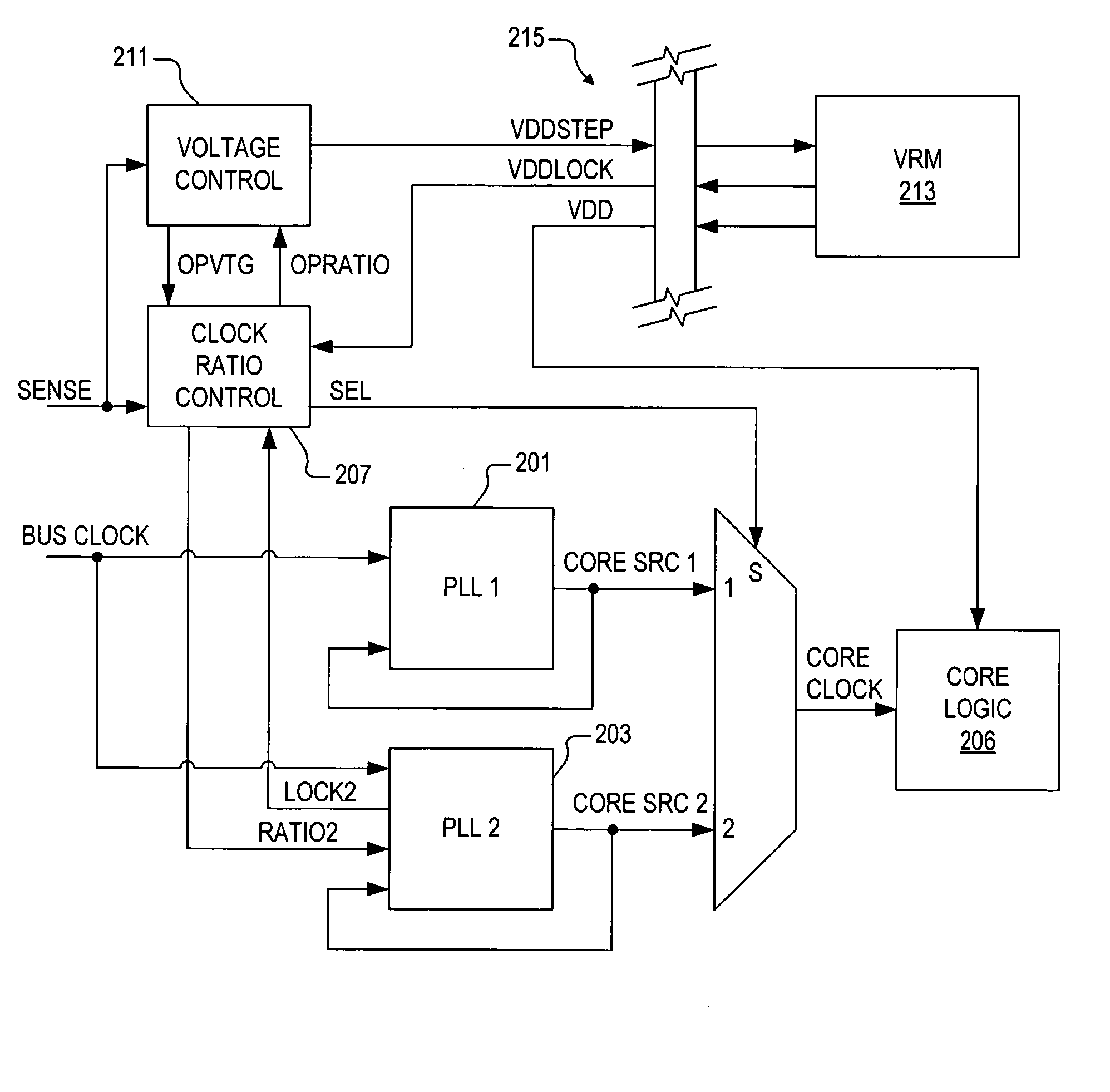
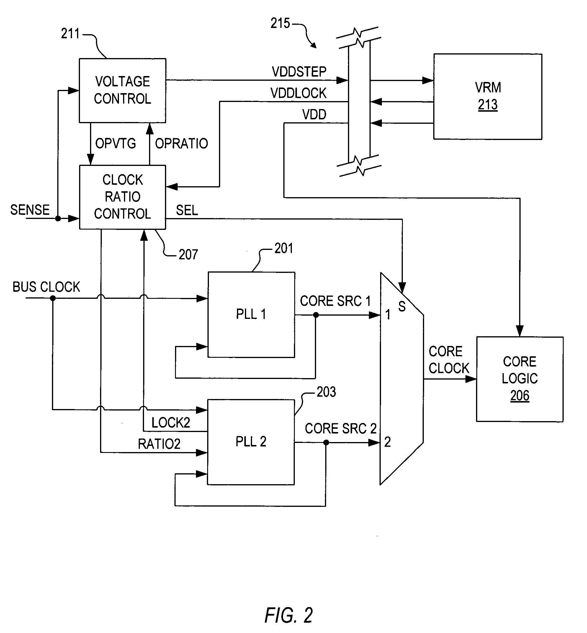
[0025] The inventors of the present application have recognized the need for changing microprocessor clock speed in a quick and seamless manner while also changing the voltage for purposes of power management. They have therefore developed an apparatus and method for frequency-voltage mechanism for microprocessor power management, as will be further described below with respe...


PUM


Abstract

A frequency-voltage mechanism for power management including first and second PLLs, select logic, control logic, and voltage control logic. The first PLL generates a first source clock signal at a first frequency based on a bus clock signal. The second PLL generates a second source clock signal at a second frequency based on a first frequency control signal and the bus clock signal. The select logic selects between the first and second source clock signals to provide a core clock signal based on a select signal. The clock control logic detects power conditions via at least one power sense signal, provides the first frequency control signal according to power conditions, and provides the select signal. The voltage control logic adjusts the operating voltage commensurate with frequency of the core clock signal. Power consumption is dynamically adjusted without undue delay while providing significant power efficiency benefits.

Description

CROSS-REFERENCE TO RELATED APPLICATIONS [0001] This application claims the benefit of U.S. Provisional Application Ser. No. 60 / 530,323, filed on Dec. 17, 2003, which is herein incorporated by reference for all intents and purposes. [0002] This application is related to the following co-pending U.S. Patent Application, which is filed on the same day as this application, which has a common assignee and at least one common inventor, and which is herein incorporated by reference in its entirety for all intents and purposes: SER.FILINGNO.DATETITLE{overscore ((CNTR.2207))}HEREWITHINSTANTANEOUS FREQUENCY-BASED MICROPROCESSORPOWER MANAGEMENTBACKGROUND OF THE INVENTION [0003] 1. Field of the Invention [0004] The present invention relates to microprocessor power management, and more particularly to providing means for dynamically adjusting the power consumed by a microprocessor in a manner that does not incur undue delays and that provides power efficiency benefits over stand-alone frequency...

Claims


Application Information

Patent Timeline
IPC IPC(8): G06F1/08G06F1/32
CPCG06F1/08G06F1/3203Y02B60/1285G06F1/3296Y02B60/1217G06F1/324Y02D10/00
Inventor GASKINS, DARIUS D.
Owner VIA TECH INC
Why Eureka
Try Eureka