Plastic intercooler

a technology of intercooler and plastic, which is applied in the direction of indirect heat exchangers, machines/engines, light and heating apparatus, etc., can solve the problems of increasing the number of joints, limiting the configuration of intercooler devices, and reducing the efficiency of intercooler construction and fabrication, so as to simplify assembly and fabrication, and eliminate significant amounts of joints

Inactive Publication Date: 2008-01-03
SIEMENS VDO AUTOMOTIVE CORP
View PDF18 Cites 24 Cited by
  • Summary
  • Abstract
  • Description
  • Claims
  • Application Information

AI Technical Summary

Benefits of technology

[0009]Another example intercooler includes a manifold from which generally U-shaped tubes extend that are attached to the manifold a...

Problems solved by technology

Disadvantageously, metal tube construction and fabrication provide a relatively heavy and cumbersome device.
Further, the use of metal tubes limits the confi...

Method used


Image

  • Plastic intercooler
  • Plastic intercooler
  • Plastic intercooler

Examples


Embodiment Construction

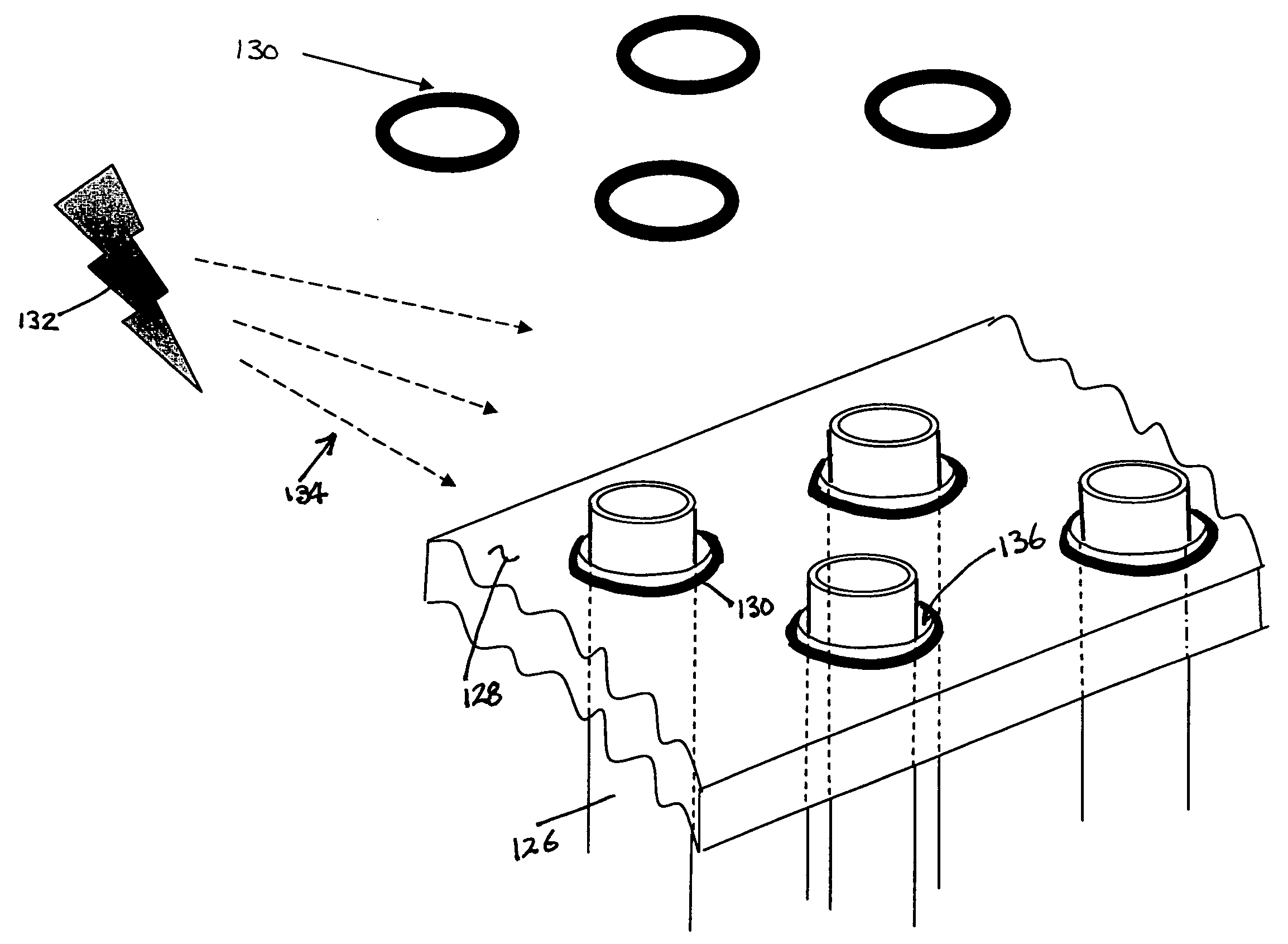
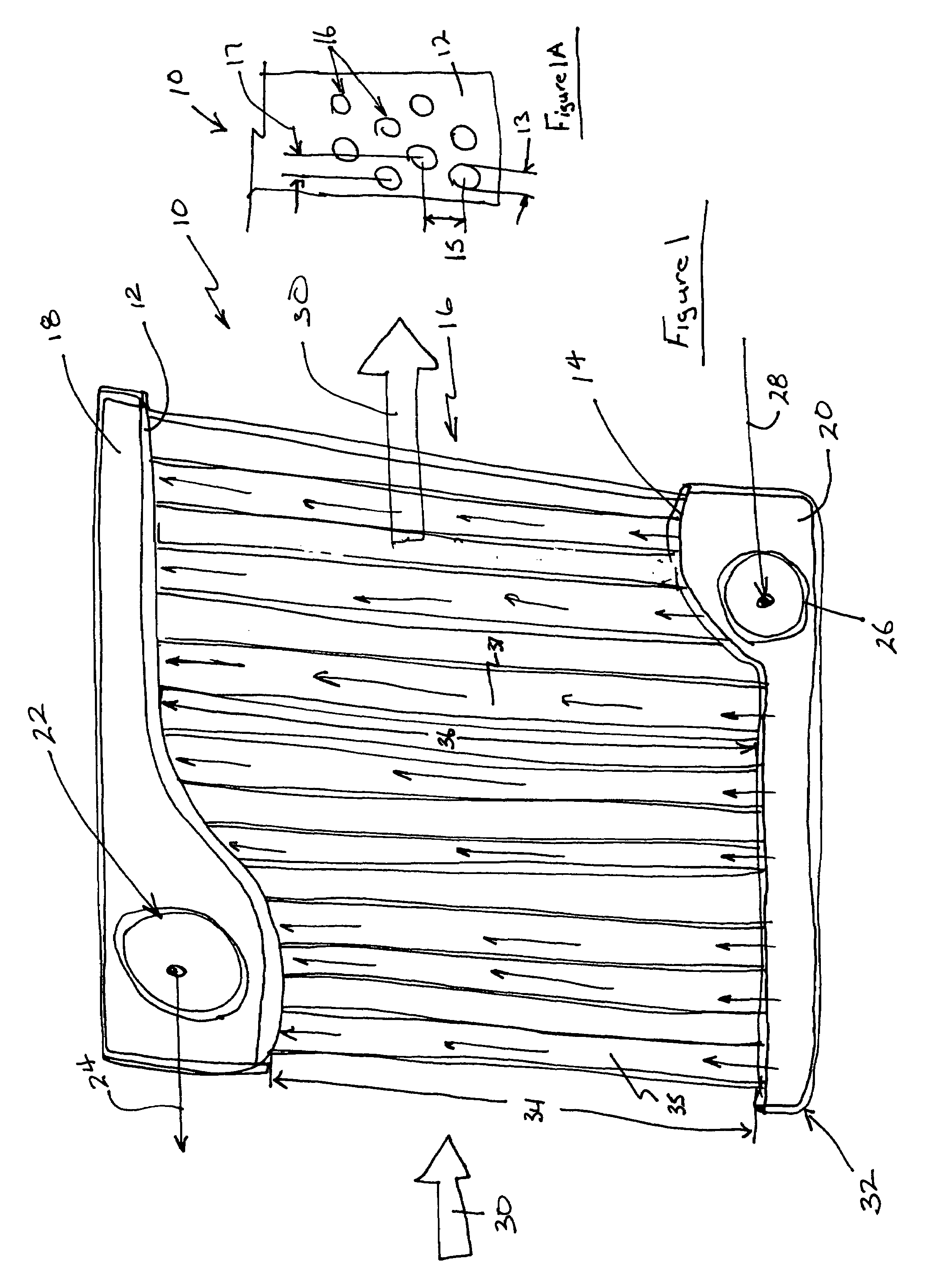
[0026]Referring to FIG. 1, an intercooler assembly 10 includes a first end plate 12 and a second end plate 14. Extending between the first end plate 12 and the second end plate are a plurality of plastic tubes 16. A first tank 18 is attached to the first end plate 12 and a second tank 20 is attached to the second end plate 14. The first tank 18 includes an opening 22 providing an outlet for exhausting air indicated by arrows 24. The second tank includes an inlet 26 for incoming air indicated by arrow 28.

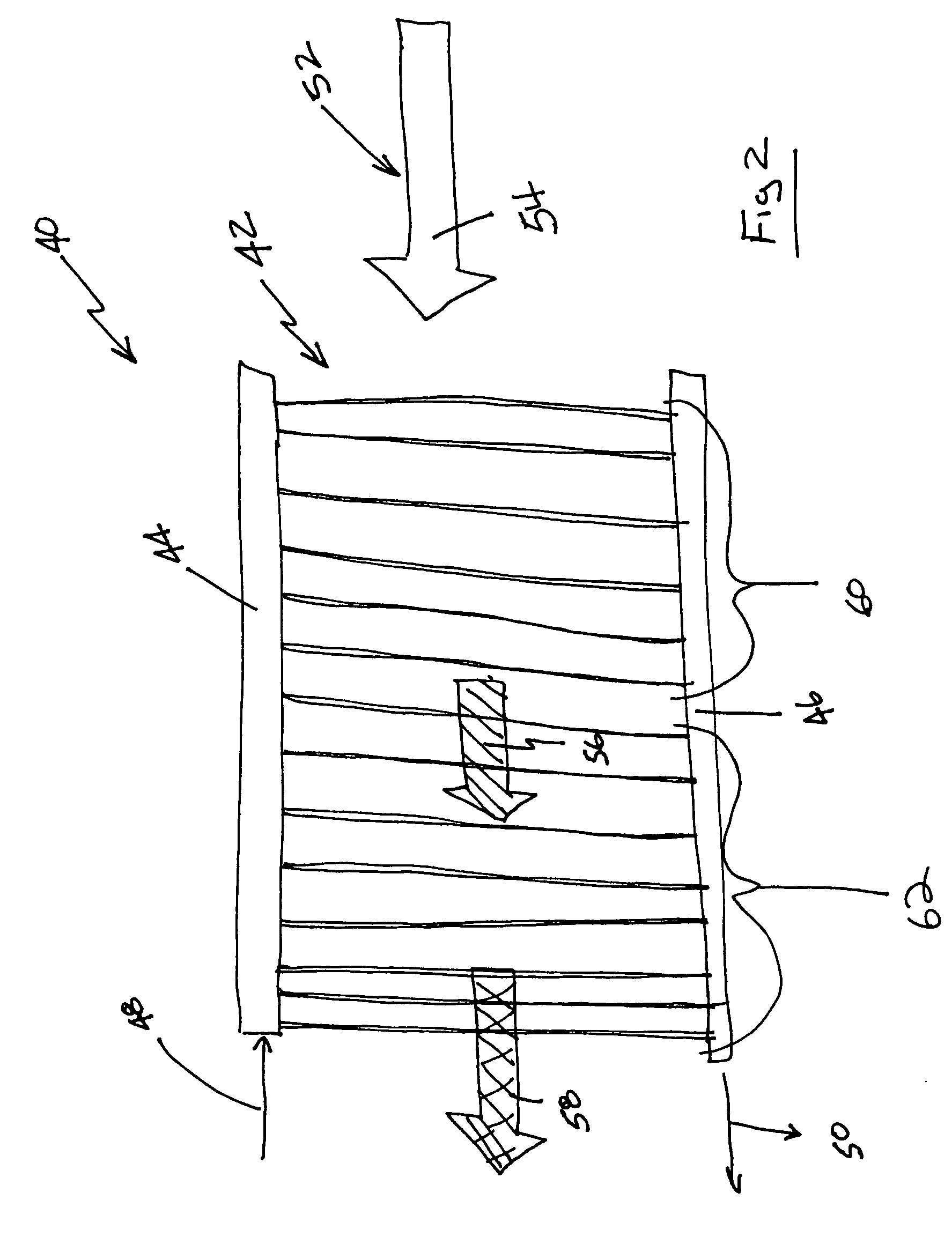
[0027]The incoming air 28 is at a high temperature and enters the inlet 26 that is in communication with the plurality of tubes 16. The high temperature air flows through the plurality of tubes 16 to the first tank 18. As the air flows through the plurality of tubes 16, a portion of the heat is rejected through the plurality of tubes 16 to a cooling stream 30 that flows across and around each of the plurality of tubes 16. The exhaust air 24 exiting the outlet 22 is therefore at a low...


PUM

PropertyMeasurementUnit
Lengthaaaaaaaaaa
Diameteraaaaaaaaaa
Electrical resistanceaaaaaaaaaa

Abstract

A plastic intercooler assembly includes a plurality of plastic tubes that extend between plastic end plates. The plastic tubes are secured to the end plates to provide the desired seal between the end plates and the ends of the tubes. The plastic tubes are attached utilizing plastic welding methods that reduce assembly time and cost.

Description

BACKGROUND OF THE INVENTION[0001]This invention generally relates to an intercooler for use in a motor vehicle. More particularly, this invention relates to a plastic intercooler and method of fabricating and assembling a plastic intercooler.[0002]An intercooler is a heat exchanger for transferring heat from one fluid into another fluid that is not physically in contact. One example application of an intercooler is for cooling turbo compressor exhaust gases prior to use in a turbocharger or as charge air. It is desired to cool the exhaust gases to reduce volume and increase the amount of charge air that can be input into the cylinder. The hot air is directed through a plurality of tubes over which cooling air flows. Heat from the hot air is transferred through the tubes and carried away by the cooler air.[0003]A conventional intercooler includes a plurality of tubes that span between manifolds or tanks on each end. The tanks typically comprise an open internal volume in communicatio...

Claims


Application Information

Patent Timeline
IPC IPC(8): F28F9/02
CPCB29C65/02Y10T29/49373B29C65/1635B29C65/1654B29C65/1664B29C65/1687B29C65/7838B29C66/21B29C66/3282B29C66/3452B29C66/53465B29C66/65B29C66/652B29K2995/0067B29L2023/005B29L2031/18B29L2031/602B29L2031/7098F02B29/0462F28D1/0475F28D1/05316F28D1/05366F28D2001/0273F28D2021/0082F28F9/18F28F21/062F28F2275/062F28F2275/064F28F2275/067Y02T10/146B29C65/3644B29C65/368B29C66/93451B29C65/0672B29C66/1222B29C66/1224B29C66/73921B29C66/8322B29K2995/0027Y02T10/12
Inventor BAYLIS, BOBBYE KAYEHARVEY, BRUCE J.MCLEAN, IAN R.DALY, PAUL D.
Owner SIEMENS VDO AUTOMOTIVE CORP
Why Eureka
Try Eureka