Modular LED lighting fixture

a technology of led lighting fixtures and modules, which is applied in the direction of fixed installation, lighting and heating equipment, lighting support devices, etc., can solve the problems of poor light quality, poor maintenance performance, dirt and other losses,

Active Publication Date: 2008-01-03
IDEAL IND LIGHTING LLC
View PDF30 Cites 140 Cited by
  • Summary
  • Abstract
  • Description
  • Claims
  • Application Information

AI Technical Summary

Benefits of technology

The patent is about a modular LED fixture that has a housing and multiple removable PCB strips with LEDs. The fixture also has a power supply that can be easily attached to the housing to power the LEDs. The technical effect of this invention is that it allows for easy customization and flexibility in the placement of LEDs, making it suitable for different lighting needs.

Problems solved by technology

The technical problem addressed in this patent text is the need for improved area lighting fixtures that can change the shape and brightness of the light output without replacing the entire fixture. This is particularly important because conventional HPS lighting fixtures are bulky and require frequent maintenance, while LED lighting fixtures offer improved efficiency and longer lifespan. The patent proposes a solution to this problem by introducing a new LED lighting fixture that can alter the pattern of the light output without replacing the entire fixture.

Method used


Image

  • Modular LED lighting fixture
  • Modular LED lighting fixture
  • Modular LED lighting fixture

Examples


Embodiment Construction

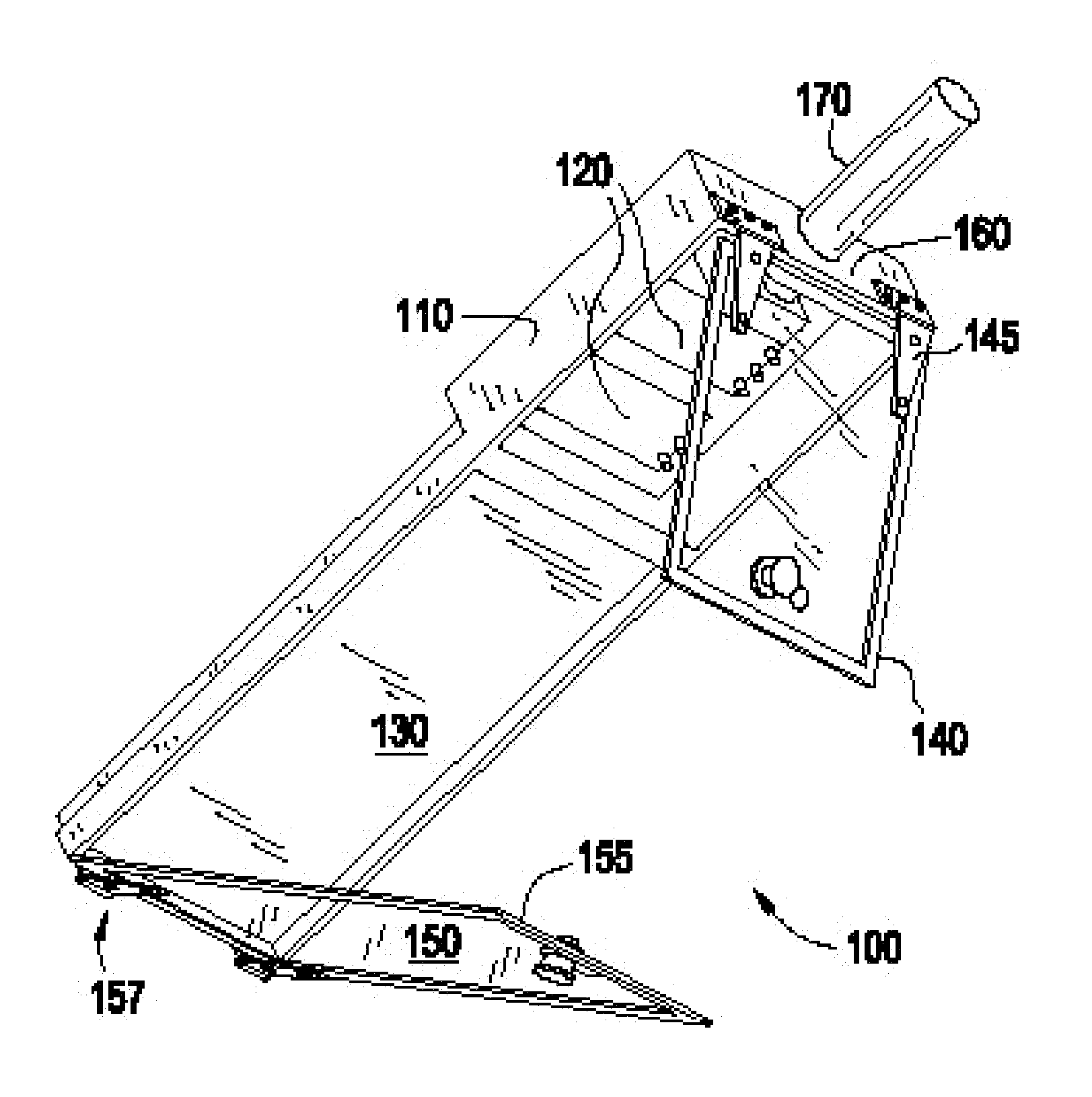
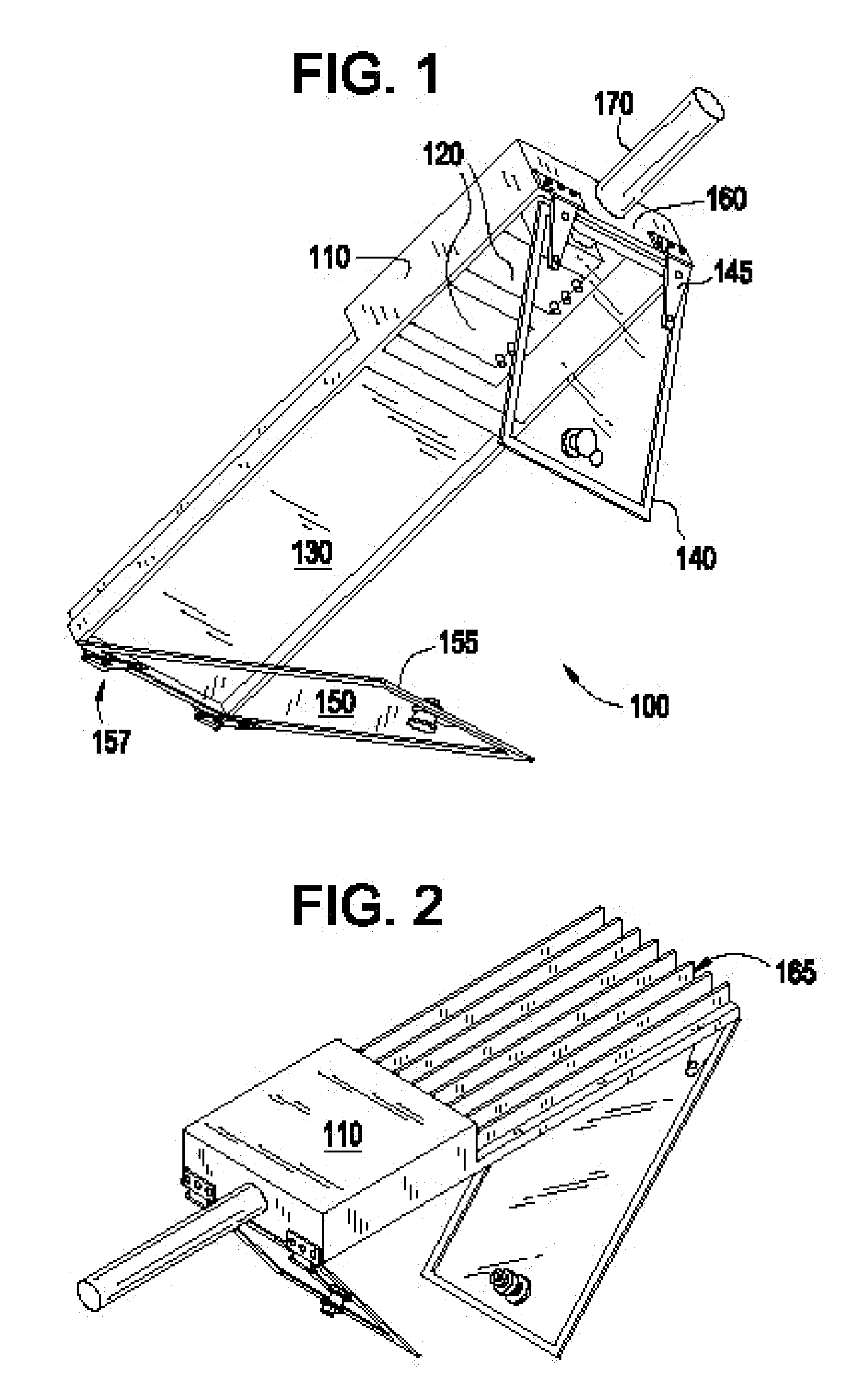
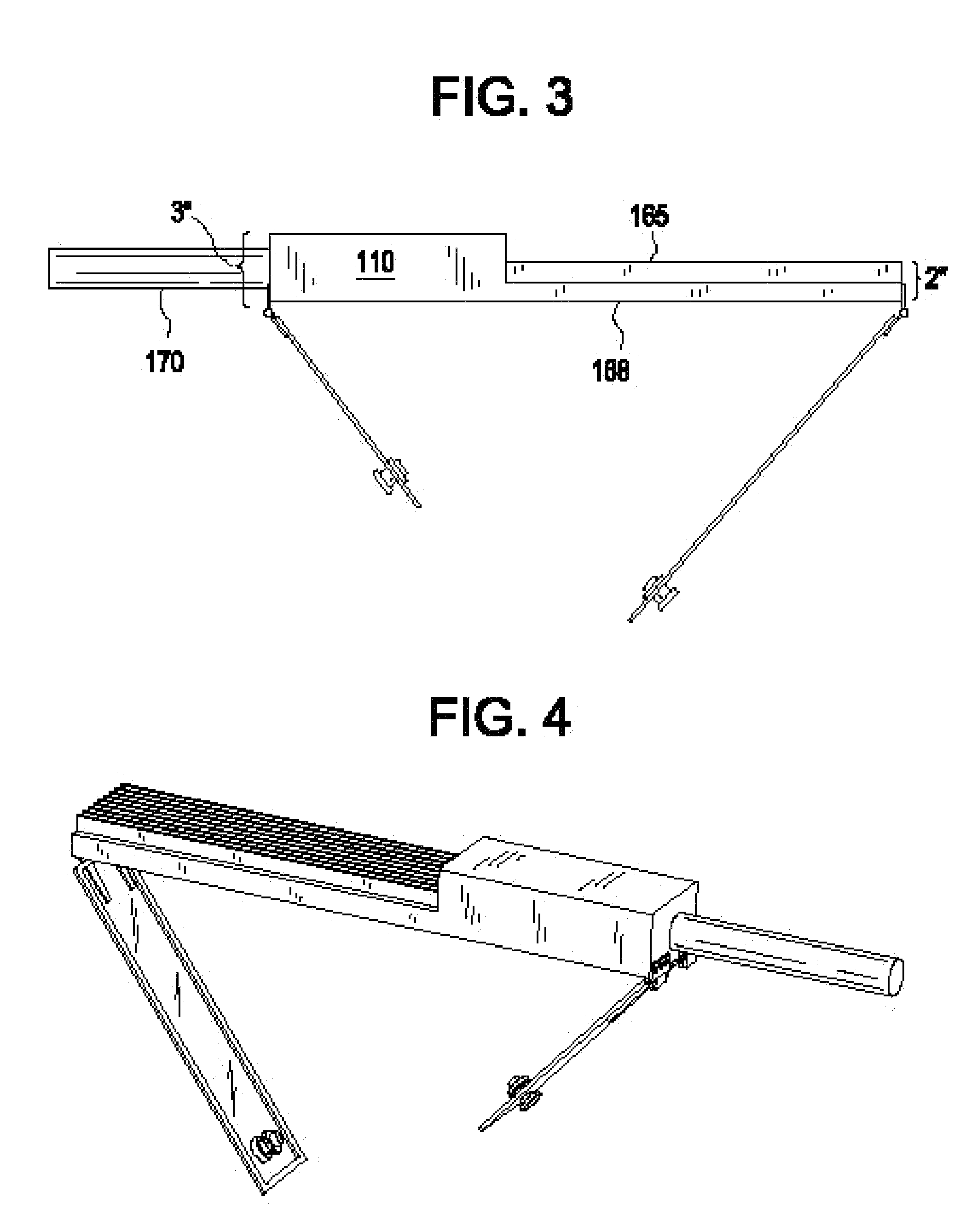
[0028]As used herein, the term “lens” or “window” may be understood as a device for either concentrating or diverging light, typically formed from a piece of shaped glass, polymer or plastic. For example, a lens as described herein may be embodied as a generally semi-spherical piece of shaped glass, polymer or plastic for concentrating or diverging light emitted from a light emitting die or LED assembly. A “flextape” as used herein may be understood as a polymer like film which in one high temperature example may be composed of a polyimide, i.e., a flexible polyimide circuit having at least one polyimide layer and at least one conductive layer within a flexible plastic resin. The conductive layer forms a metal trace connected to LED or LED assembly or array.

[0029]An LED package can be synonymous with an LED module for the following discussion. Additionally, the modular LED fixture including replaceable LED modules and power supplies may be applicable in general to area lighting appl...


PUM


Abstract

A modular LED lighting fixture is provided, where the shape and brightness of light output from the fixture can be altered by changing LED modules and/or power supplies powering the modules within the fixture. The fixture can include a housing, a modular, removable LED module attached within the housing, and at least one modular, removable power supply attached to the housing for powering the LED module.

Description


Claims


Application Information

Patent Timeline
Owner IDEAL IND LIGHTING LLC
Why Eureka
Try Eureka